346 Agilent X-Series Signal Generators User’s Guide
Custom Digital Modulation (Option 431)
Using the Arbitrary Waveform Generator
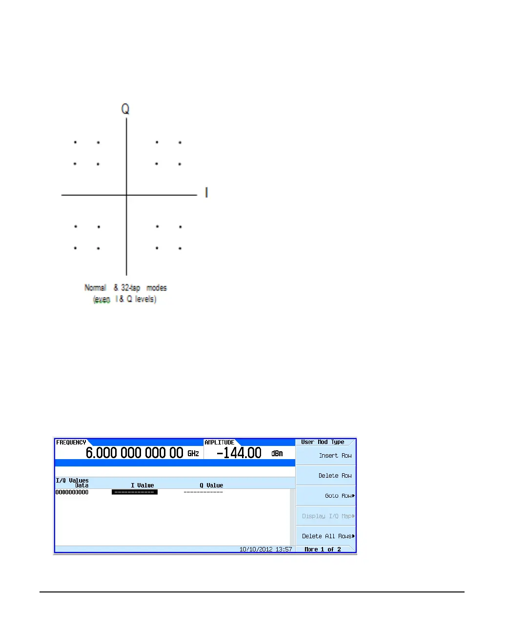
Figure 13-23 I/Q Constellation Diagram
By modulating the carrier to one of several predetermined positions in the I/Q plane, you can then
transmit encoded information. Each position or state represents a certain bit pattern that can be
decoded at the receiver. The mapping of the states at each symbol decision point on the I/Q plane is
referred to as a constellation diagram. You can create a unique signal by mapping your constellation
diagram into the I/Q table editor, shown in Figure 13- 24. The table editor also has a display feature,
which provides a quick visual check of the expected I/Q constellation.
Figure 13-24 I/Q Table Editor
For details on each key, use key
help as described on page 44.
Mode > Real-Time Custom Modulation > Modulation Setup > Modulation Type > Define User I/Q

 Loading...

