Page 468 7750 SR OS Services Guide
MAC Flush Additions for PBB VPLS
The scenario depicted in Figure 70 is used to define the blackholing problem in PBB-VPLS using
MC-EP.
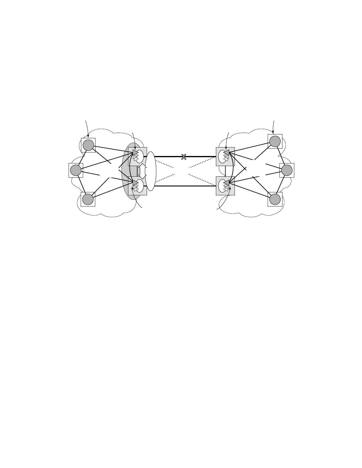
Figure 70: MC-EP with B-VPLS Failure Scenario
In topology displayed in Figure 70, PE A and PE B are regular VPLS PEs participating in the blue
VPLS mesh deployed in the metro and respectively WAN region. As the traffic flows between CEs
with CMAC X and CMAC Y, the FIB entries in blue are installed. A failure of the active PW1 will
result in the activation of PW4 between PE3 and PE2 in this example. An LDP flush-all-but-mine
will be sent from PE3 to PE2 to clear the BVPLS FIBs. The traffic between CMAC X and CMAC
Y will be blackholed as long as the entries in red from the VPLS and I-VPLS FIBs along the path
are not removed. This may take as long as 300 seconds, the usual aging timer used for MAC
entries in a VPLS FIB.
A MAC flush is required in the I-VPLS space from PBB PEs to PEA and PEB to avoid
blackholing in the regular VPLS space.
In the case of a regular VPLS the following procedure is used:
• PE3 sends a flush-all-from-me towards its local blue IVPLS mesh to PE3 and PEA when
its MC-Endpoint becomes disabled
• PE3 sends a flush-all-but-mine on the active PW4 to PE2 which is then propagated by PE2
(propagate-mac-flush must be on) to PEB in the WAN IVPLS mesh.
OSSG319
WANMetro Region
Resilient Inter-domain Handoff
VPLS
(Mesh)
VPLS
(Mesh)
PE3
PEA
PEB
CMAC X
CMAC Y
PE3’
PE1
PE2
MC
EP
B
B
B
B
PW1
PW4
Standby PWs
X
-
>SAP2
Y
-
>PWtoPE3
X
-
>PWtoPE1
Y
-
>SAP1
X
-
>PWtoA
Y
-
>BM1
-
>PW1
X
-
>BM3
-
>PW1
Y
-
>PWtoB
X
-
>PWtoA
Y
-
>PWtoPE3
X
-
>PWtoPE1
Y
-
>PWtoB