Virtual Private LAN Services
7750 SR OS Services Guide Page 459
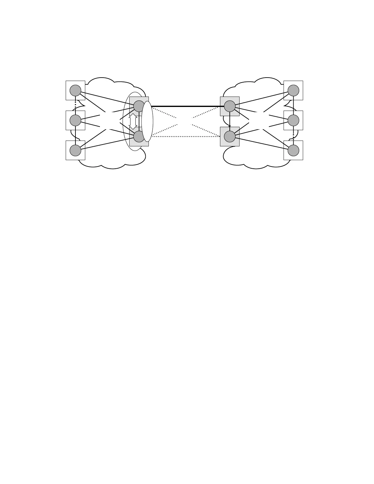
Figure 66: Multi-Chassis Pseudowire Endpoint for VPLS
The two gateway pairs, PE3-PE3and PE1-PE2, are interconnected using a full mesh of four
pseudowires out of which only one pseudowire is active at any point in time.
The concept of pseudowire endpoint for VPLS provides multi-chassis resiliency controlled by the
MC-EP pair, PE3-PE3 in this example. This scenario, referred to as multi-chassis pseudowire
endpoint for VPLS, provides a way to group pseudowires distributed between PE3 and PE3
chassis in a virtual endpoint that can be mapped to a VPLS instance.
The MC-EP inter-chassis protocol is used to ensure configuration and status synchronization of
the pseudowires that belong to the same MC-EP group on PE3 and PE3. Based on the information
received from the peer shelf and the local configuration the master shelf will make a decision on
which pseudowire will become active.
The MC-EP solution is built around the following components:
• Multi-chassis protocol used to perform the following functions:
→ Selection of master chassis.
→ Synchronization of the pseudowire configuration and status.
→ Fast detection of peer failure or communication loss between MC-EP peers using
either centralized BFD if configured or its own keep-alive mechanism.
• T-LDP signaling of pseudowire status:
→ Informs the remote PEs about the choices made by the MC-EP pair
• Pseudowire data plane — Represented by the four pseudowires inter-connecting the
gateway PEs.
OSSG250
WANMetro Region
Resilient Inter-domain
Handoff
VPLS
(Mesh)
VPLS
(Mesh)
PE3
PE3’
PE1
PE2
MC
EP
Active PW
Standby PWs