EasyManuals Logo

Allen-Bradley ControlLogix User Manual

Allen-Bradley ControlLogix
203 pages
To Next Page IconTo Next Page
To Previous Page IconTo Previous Page
Page #90 background imageLoading...
Page #90 background image
1756-6.5.3 - December 1999
6-18 Logix5550 Controller to PLC-5C: Scheduled Communications
To verify that the message is being received by the PLC-5C processor, you
must examine the input file configured in RSNetWorx for ControlNet (i.e.,
N9).
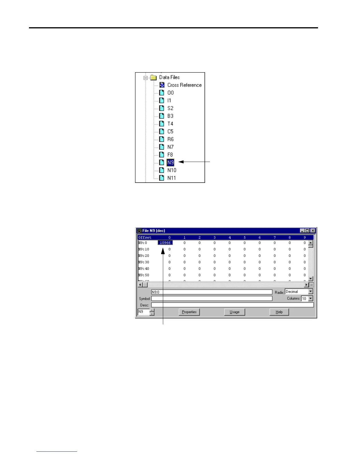
14.Double-click on file N9 in the Data Files folder.
You should see the value in N9:0 continuously changing to reflect the
data from the Logix5550 controller.
This completes the Logix5550 to PLC-5C scheduled communication
example.
Examine this file.
This value should be changing.

Table of Contents

Other manuals for Allen-Bradley ControlLogix

Questions and Answers:

Question and Answer IconNeed help?

Do you have a question about the Allen-Bradley ControlLogix and is the answer not in the manual?

Allen-Bradley ControlLogix Specifications

General IconGeneral
CommunicationEtherNet/IP, ControlNet, DeviceNet, DH+
I/O CapacityUp to 128, 000 I/O points (varies by configuration)
RedundancySupported (with specific modules)
Programming SoftwareRockwell Automation Studio 5000 Logix Designer
Operating Temperature0°C to 60°C (32°F to 140°F)
Programming LanguagesLadder Logic, Function Block Diagram, Structured Text, Sequential Function Chart
ModularityYes
CertificationsUL, CE
Processor TypeMultiple options available, including standard, safety, and extreme environment processors
Power SupplyMultiple options available, including standard and redundant power supplies with various voltage ranges (e.g., 24V DC, 120/240V AC)

Related product manuals