Chapter 5 Parameter Introductions
104
14: Forced outage (Dec to stop within Dec time 4)
36: Forced outage normally close
The inverter stops according to Dec time 4, and decided by P1.08 (stop mode).
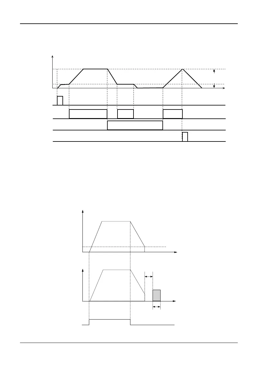
Operation Freq.(Hz)
UP/DOWN
reference
Initial
Run Command
UP command
DOWN
Command
Stop
command
UP/DN reference
amplitude
Fig. 5-3-4 UP/DOWN non-combination operation diagram
15: DC injection braking
If the function of terminal is defined as set DC injection braking, the terminal can
be used to perform DC injection braking. DC injection braking frequency at start,
DC injection braking time at start and DC injection braking current are defined by
P1.09~P1.11. Braking time is the max of P1.12 and the last time during which the
DC injection braking control terminal is active. As shown in Fig. 5-3-5.
Output Freq.(Hz)
initial frequency
DC injection braking
Output Voltage
Braking energy
Time
Run Command
Waiting time for
DC injection
braking
Braking time
Braking energy
Fig. 5-3-5 DC injection braking