Chapter 5 Parameter Introductions
84
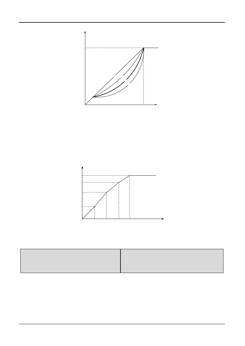
Ooutput Voltagey(V)
Output Frequency(Hz)
Max output
Voltage (P0.10)
Basic Frequency (P0.06)
0
3
2
1
Fig. 5-0-2 Torque-reducing curve
If P0.12 is set to 4, you can define V/F curve by P0.13~P0.18, as shown in Fig. 5-0-3.
The V/F curve can be defined with 4 points to meet special load characteristics demand.
Voltage %
Frequency (Hz)
P0.14
P0.16
Basic Frequency
(P0.06)
P0.18
100%
P0.13 P0.15 P0.17
Fig. 5-0-3 V/F-curve defined by user
P0.19 Torque boost mode
Range: 0.0~3 0.0%
【S2R4GB~3004GB/35R5PB:40%;
35R5GB/37R5PB and above:0.0%】
Note:
In order to compensate the torque dropping at low frequency, the inverter can boost the
voltage to boost the torque. If P0.19 is set to 0, magnetic flux vector modulation is
enabled and if P0.19 is set to non-zero, manual torque boost is enabled, as shown in Fig.
5-0-4.