Chapter 2 Installation and Wiring
32
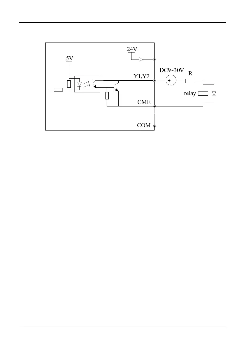
6)Multi-function output terminals Y1 and Y2 can also use the external 9~30V power
supply and the wiring method is shown in Figure 2-31.
Fig. 2-31 Wiring method 2 of multi-function output terminal
(only 35R5GB/37R5PB~3500G)
Wiring of Relay Output Terminals TA, TB, TC and BRA, BRB, BRC (BRA, BRB,
BRC is provided only in 35R5GB/37R5PB~3500G)
If the inverter drives an inductive load (such as relay or contactor), then a surge
suppressing circuit should be added, such as RC snub circuit, lightning varistor or a
flywheel diode (used in the DC electric-magnetic circuit and pay attention to the polarity
during installation). Snubbing components should be as close to the coils of relay or
contactor as possible.
Notes:
Don’t short circuit terminals 24V and COM, otherwise the control board may be
damaged.
Please use multi-core shielded cable or multi-stranded cable (above 1 mm) to connect
the control terminals.
When using a shielded cable, the shielded lay’s end that is nearer to the inverter should
be connected to PE.
The control cables should be as far away(at least 30 cm) from the main circuit and
high-voltage cables as possible (including power supply cables, motor cables, relay
cables and cables of contactor). The cables should be vertical to each other to reduce
the disturbance to minimum.
Keyboard Interface
Keyboard Interface of CN2 on the control board uses standard 8PIN interface, which is
shown in Figure 2-32. Users can order the extended keyboard cable or make it by
themselves according to actual need. Be sure that the extension cable of the keyboard is