Chapter 5 Parameter Introductions
130
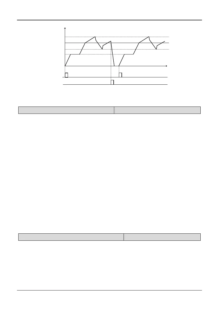
Time(S)
Operation Freq.(Hz)
Central Freq.
Preset Freq.
Run command
Stop command
Fig. 5-6-3 Wobble frequency start: Restart
5.8 PID Control (Group P7)
P7.00 PID feed selection
Range: 0~4【1】
0: PID digital input 1: AI1 terminal
2: AI2 terminal 3: Pulse frequency
4: Serial communication
Note:
P7.00 is used to define the input method and channel of PID feed. It can be a digital
input (0, 4). It can also be an analog input (1, 2, 3). The digital input is more
accurate and stable. Analog input curve can be defined by parameter group P4.
If P7.00 is set to 0, there are 2 kinds of sources for PID digital input: “Analog PID
digital feed” (P7.02) and “speed PID feed” (P7.03). If “Feedback selection” (P7.01)
is set to 9, “speed PID feed” (P7.03) will be treated as PID digital feed. Besides that,
“analog PID digital feed” (P7.02) will be treated as PID digital feed.
AI1/AI2 terminal: PID feed by analog input. Dial the voltage and current switches
to select the terminal as a 0~10V or 0~20mA analog input. For details, please refer
to the basic operating wiring connections in 2.6.
Serial communication: PID feed will be set by the host PC through RS485 serial
communication. If analog PID is used, the setting must be based on the percentage
of the measuring range. If speed PID is used, the setting value must be based on the
percentage of the largest speed.
P7.01 PID feedback selection
Range: 0~9【1】
0: AI1 terminal 1: AI2 terminal
2: Serial communication 3: Pulse feedback
4: |AI1-AI2| 5: Reserved
6: AI1+AI2 7: MIN (AI1, AI2)
8: MAX (AI1, AI2)
9: PG or single-phase speed
measuring input
Note: