Chapter 2 Installation and Wiring
24
Inverter
Shielded wire
rear Grounding
or
Fig 2-16 35R5GB/37R5PB~3500G Analog output terminal wiring diagram
Notes:
1) Dialing SW1, SW2, SW3 to “I” represents current, dialing to “V” represents
voltage.
2)Analog input and output signals are easily disturbed by exterior environment, so
shielded cables must be used for wiring and the length of the cables should be as short
as possible.
3)When an analog output equipment is connected to the inverter, sometimes because of
error act because of interference caused by the analog output equipment or the inverter,
when which happens, a 0.01~0.1uF/50V capacitance or a ferrite bead (enwind 3 laps)
could be connected to the analog output equipment.
Wiring of Serial Communication Interface
The inverter of this series provides standard RS485 serial communication interface for
users, which can be composed as master and slave network. By using a host PC or PLC,
the inverter in the network can be monitored in real time and controlled remotely and
automatically, thus more complicated operation control can be realized.
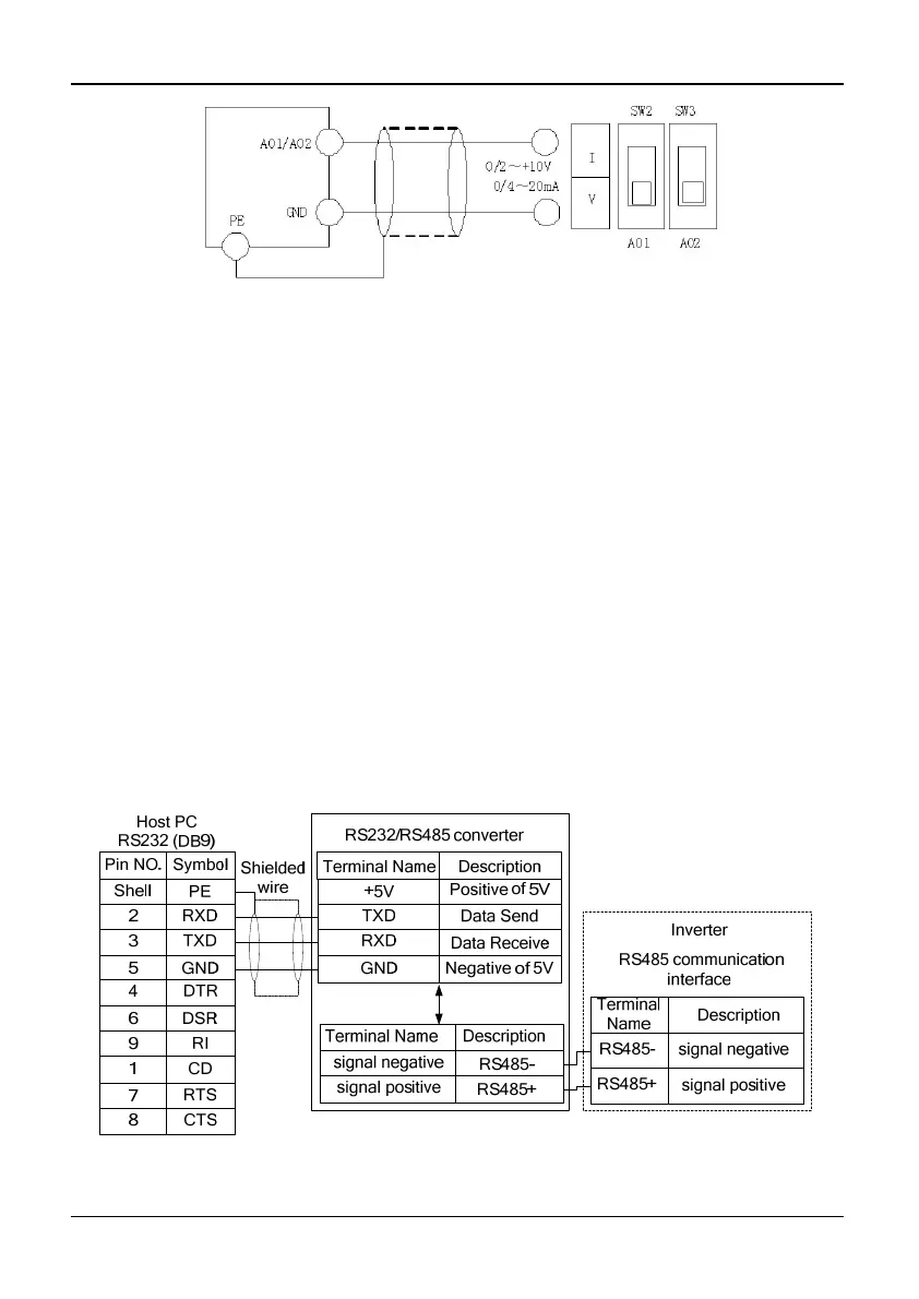
Connection between the inverter and the host PC:
Fig. 2-17 Connection between the inverter and the host PC