Chapter 5 Parameter Introductions
139
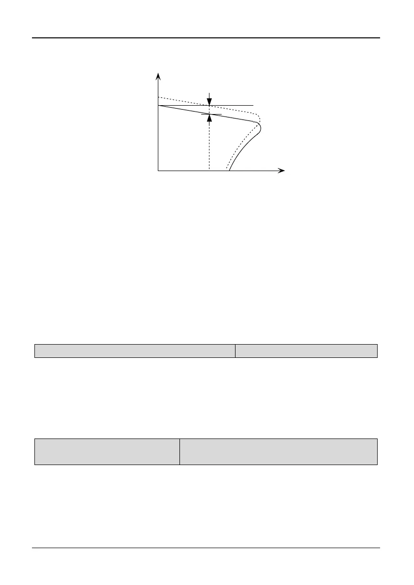
slip compensation according to the load torque. Therefore, the electrical
characteristics of the mechanical hardness are improved. As shown in Fig. 5-9-1.
Synchronous
speed
n
T
Freq. after
compensation
Compensation Freq.
f
Load torque
Fig. 5-9-1 Auto slip compensation diagram
In rated torque state, the value of slip compensation is: Gain of Slip Frequency
compensation (P9.00) * Rated slip (Synchronous speed- Rated speed)
Electro motion state: Increase the gain of slip compensation (P9.00) gradually
when the actual speed is lower than the reference speed.
Generating state: Increase the gain of slip compensation (P9.00) gradually when the
actual speed is higher than the reference speed.
Tips:
The value of automatically slip compensation is dependent on the motor’s rated slip;
therefore, the motor rated speed (PA.08) must be set correctly.
Slip compensation is disabled when P9.00 is set to “0”.
P9.02 Energy saving control selection
Range: 0,1【0】
0: Disabled 1: Enabled
Note:
The energy saving control parameters have been preset at the factory to the
optimum values. It is not necessary to adjust them under normal operation. If your
motor characteristic has great difference from those of standard induction motors,
refer to the following description to adjust the parameters.
P9.03 Energy saving gain
coefficient
Range: 0.00~655.3【This value depends on the
inverter model】
Note:
The energy saving gain coefficient used in the energy saving control mode is for
calculation of the voltage at which motor efficiency will be the greatest, and set the
voltage as the output voltage reference. The value of P9.03 is preset according to
the standard induction motor before delivery. When the energy saving gain
coefficient increases, the output voltage will increases.