Chapter 5 Parameter Introductions
120
%
Min analog
value (V)
Max analog
value (V)
Physical value
corresponding to Min
analog value Input
%
Physical value
corresponding to Max
analog value Input
%
%
Min analog
value (V)
Max analog
value (V)
Physical value
corresponding to Min
analog value Input
%
Physical value
corresponding to Max
analog value Input
%
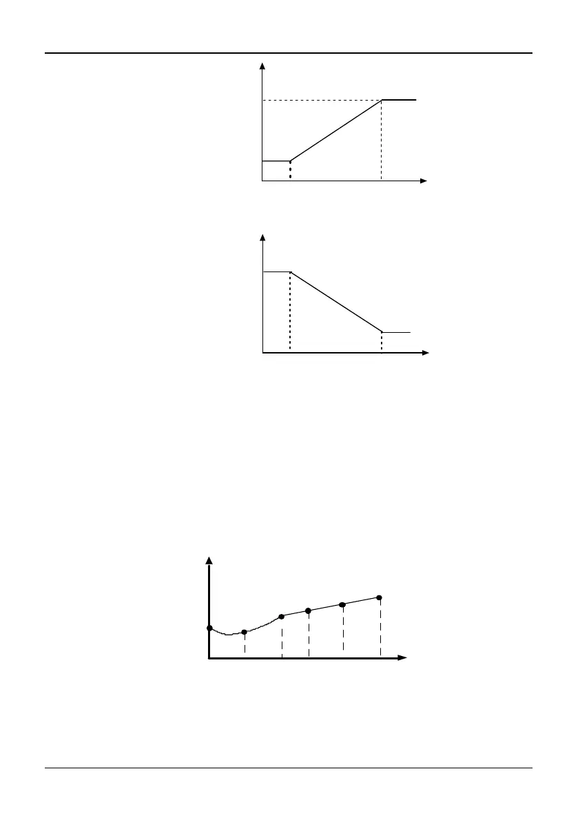
Fig. 5-4-1 Analog input linear curve
Note 2:
When P4.00 is set to 1, 2, or 3, the function of P4.01~P4.04, P4.06~P4.09 and
P4.11~P4.14 are combined for one physical value, which is different to Note 1.
User can define their own nonlinear curves by setting these parameters. Six points
can be set on the curve. As shown in Fig. 5-4-2. In addition, the setting value to
P4.01, P4.03, P4.06, P4.08, P4.11, P4.13 must increase in order.
Physical value corresponding
to analog value Input%
P4.08P4.03
P4.13
P4.01
P4.11P4.06
Analog
input
P4.02
P4.04
P4.07
P4.09
P4.14
P4.12
Fig. 5-4-2 Analog input non-linear curve
Note 3:
The input filter time constant is used for digital filter of the input signal, in order to
avoid interference of the system.