Chapter 5 Parameter Introductions
116
P3.20 Frequency detection hysteresis
values (FDT lag)
Range: 0.00~10.00Hz【1.00Hz】
Note:
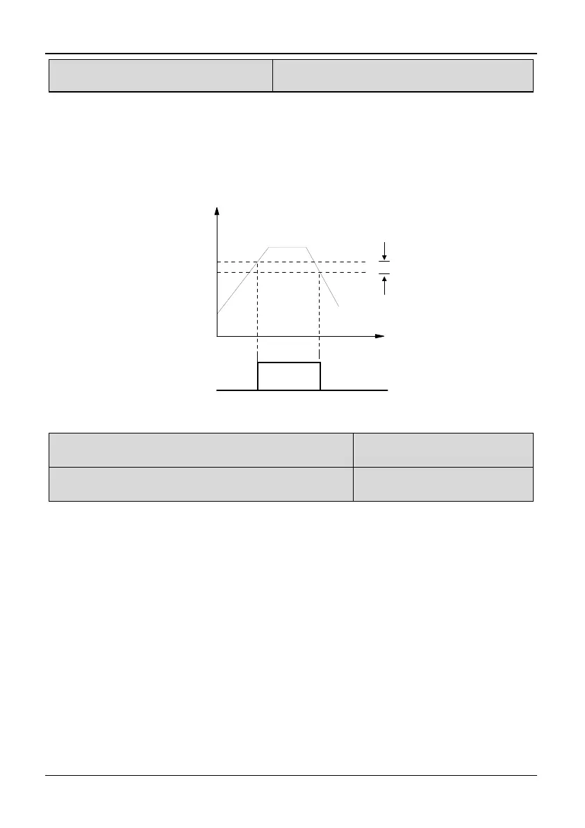
When the output frequency reaches a certain preset frequency (frequency detection
threshold), Y terminal output will be valid. We called the preset frequency FDT
level. In the dropping of output frequency, Y terminal output keep valid, until the
output frequency drops below another certain frequency of FDT level, which is
called release frequency (FDT1 level-FDT1 lag), as shown in Fig. 5-3-9.
FDT lag
Time
Time
FDT level
Output Freq.
FDT signal
Fig. 5-3-9 FDT level and lag diagram
P3.21 Frequency upper limit arriving output delay
time
Range: 0.0~100.0s【0.0s】
P3.22 Frequency lower limit arriving output delay
time
Range: 0.0~100.0s【0.0s】
Note:
For 35R5GB/37R5PB and the above models: function of P3.13 ~ P3.17 will be D0,
Y1, Y2. Relay 1and relay 2 outputs have been set as 4 (FDTH: Frequency upper
limit arriving) or 5 (FDTL: Frequency lower limit arriving).
For 3004GB/35R5PB and the below models: function of P3.13 and P3.16 will be
D0. Relay output has been set as 4 (FDTH: Frequency upper limit arriving) or 5
(FDTL: Frequency lower limit arriving).
Usually, this Function is valid to avoid load wobbling and signal instability when
several motors switch between commercial frequency and conversion frequency, as
shown in Fig. 5-3-10.