Chapter 5 Parameter Introductions
141
voltage will keep constant within the inverter output capacity.
P9.08 Over modulation enable
Range: 0, 1【0】
0: Disabled
1: Enabled
Note:
When the over modulation function is enabled, the inverter voltage output capacity
can be improved. However, if the output voltage is too high, the output current
harmonics will increase.
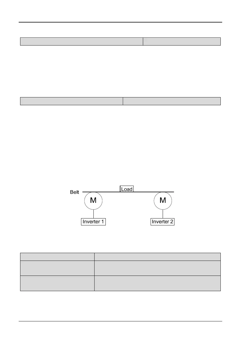
P9.09 Drop control (load distribution)
Range: 0.00~10.00Hz【0.00Hz】
Note:
When several inverters drive one load at the same time, the function will make the
inverters share the load equally.
When the load current of one inverter is greater (>50%), this inverter will reduce its
output frequency to shed part of the load according to the settings of this parameter.
Once the load current is below 50% (<=50%), the inverter will stop reducing its
output frequency. If the load current has been greater than 50%, the output
frequency reduces until the difference between reference frequency and P9.09.
Tips:
Slip compensation and drop control cannot be used at the same time. Slip
compensation has priority.
Fig. 5-9-3 Drop control
5.11 Motor Parameters (Group PA)
PA.00 Motor polarity number
Range: 2~56【4】
PA.01 Rated power
Range: 0.4~999.9kW【This value depends on the
inverter model】
PA.02 Rated current
Range: 0.1~999.9A【This value depends on the
inverter model】
Note:
PA.00, PA.01 and PA.02 are used to set the motor parameters. In order to ensure
the control performance, please set PA.00~PA.02 with reference to the values on
the motor nameplate.