Chapter 5 Parameter Introductions
138
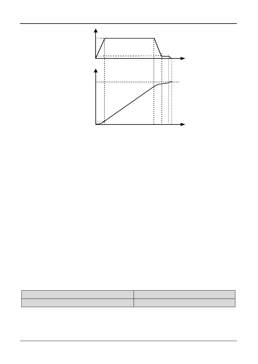
P8.00+P8.06
t
L
P0.21
t
f
P0.00
P0.09
P0.21
actual frequency
Deceleration
point
sliding
stop
overshoot
P8.00
Actual Length
Fig. 5-8-2 Fixed length control diagram 2
Tips:
The actual length can be cleared by multi-function input terminal (Define terminal Xi
as No.52 function). The actual length will calculate only when this terminal is
disconnected.
Actual length (setting of P8.01) will be saved automatically when the power is off.
When actual length P8.01 is 0, if the operation frequency is higher than frequency
lower limit but still no pulse input after running over 30 seconds, the inverter reports
pulse coder fault (dE) and stop.
If P8.00 is set to 0, function of stop at fixed length is disabled, but the calculated length
is still effective.
The setting value must increase 200.0mm when P8.06 is modified by MODBUS
communication. The corresponding relation between communication value and actual
value (displayed on the keyboard) is as follows:
Actual value (displayed on the keyboard)) = Communication value setting – 200.0mm
5.10 Advanced Control (Group P9)
P9.00 Gain of slip frequency compensation
Range: 0.0~250.0%【0.0%】
P9.01 Slip compensation time const
Range: 0.01~2.55s【0.20s】
Note:
The motor's slip changes with the load torque, which results in the variance of
motor speed. The inverter output frequency can be adjusted automatically through