Chapter 2 Installation and Wiring
23
2.5.2 Control Circuit Wiring
●Wiring Analog Input Terminal
AI1/AI2 terminals can accept analog signal input, operate Data-chosen-switch SW1 to
select input voltage (0~10V) or input current (0~20mA). The wiring is shown as Figure
2-14:
0~+10V
Or 0~20mA
GND
AI1/AI2
PE
1 2
ON
AI1 AI2
I
V
Shielded wire near
Grounding
SW1
Inverter
Fig. 2-14 Analogy input terminal wiring diagram
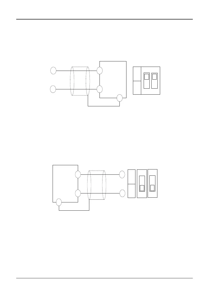
Wiring Analog Output Terminal
In S2R4GB~3004GB/35R5PB, if the analog output terminal AO1 is connected to analog
meters, the various kinds of physical values can be indicated. Operate wiper switch SW2
to select output voltage (0/2~10V) or output current (0/4~20 mA). The wiring is shown
as Figure 2-15:
SW2 SW3
AO1 AO2
I
V
0/2~+10V
Or 0/4~20mA
GND
AO1/AO2
Shielded wire
near Grounding
Inverter
PE
Fig. 2-15 S2R4GB~3004GB/35R5PB Analog output terminal wiring diagram
To indicate different kinds of physical values, for models of 35R5GB/37R5PB~3500G,
analog meters can be connected to the analog output terminals of AO1 and AO2. Switch
SW2 and SW3 on and off to select output voltage (0/2~10 V) or current (0/4~20 mA).
The wiring is shown as Figure 2-16: