Chapter 2 Installation and Wiring
26
3)Mount a toroid to the communication cable, or reduce the carrier frequency if the local
conditions permit .
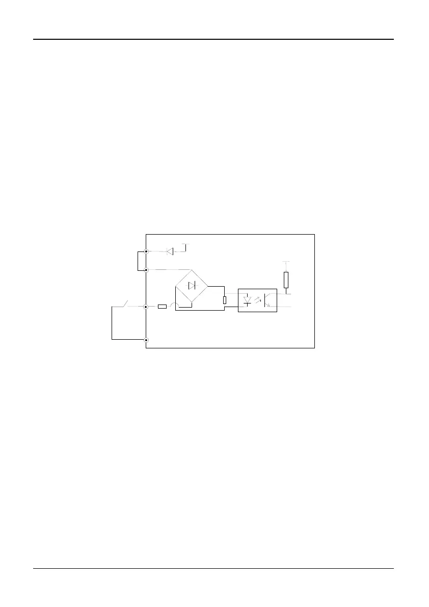
Wire Multi-Function Input Terminals
Multi-function input terminals of the inverter use a full-bridge rectifying circuit. PLC is
the common terminal of terminals X1~X8(in 3R75GB/31R5PB~3004GB/35R5PB only
X1~X5). The current flows through terminal PLC can be pulling current, and feeding
current. Wiring X1~X8 are flexible and the typical wiring is shown below:
Method 1 of connections (Dry contacts)
1)If internal 24V power supply is used, the wiring is shown in Figure2-20(Attention:
PLC and 24V must be firmly connected).
Fig. 2-20 Using Internal 24V Power Supply(in 3R75GB/31R5PB~3004GB/35R5PB
only X1~X5)
2)If an external power supply is used, then use the Wiring shown in Figure 2-21
(Attention: be sure to disconnect the cable JP1 between PLC and 24V for models of
3R75GB/31R5PB~3004GB/35R5PB; and disconnect the wiring cable between PLC
and 24V for models of 35R5GB/37R5PB~3500G).
COM
+24V
X1~X8
PLC
5V
K