Chapter 3 Operation
43
key Name of key Key functions
Direction switch
key
Press this button to change the direction of
rotation. See P0.05 function description for
details.
STOP
RESET
Stop/Reset key
In keypad control mode, this key is used to stop
the inverter. Clear the failure and return to
normal state when there is a failure.
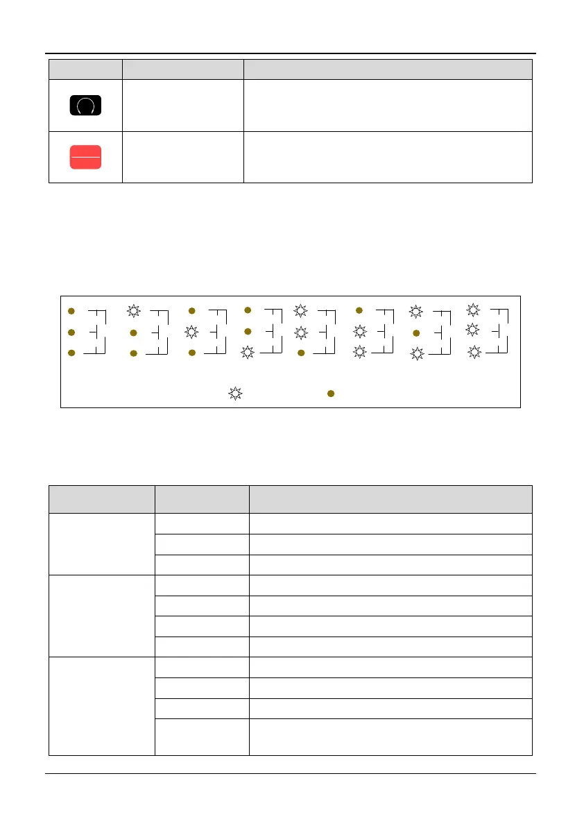
3.1.3 Description of LED Digitals and Indicators
On the inverter keyboard there are four digitals seven segments LEDs, 3 unit indicators,
5 status indicators. The four digitals can display the monitoring object, the function
parameter values and the fault code, the warning code. The three unit indicators have
eight combinations, and each combination corresponds to one-unit. The combinations
and their corresponding units are as the following:
Hz A Vno unit
ON OFF
r/min
m/s
%A
V
Hz
r/min
m/s
%A
V
Hz
r/min
m/s
%A
V
Hz
r/min
m/s
%A
V
Hz
%
r/min
m/s
%A
V
Hz
r/min
r/min
m/s
%A
V
Hz
m/s
r/min
m/s
%A
V
Hz
PID
r/min
m/s
%A
V
Hz
Figure 3-2 Combinations of unit indicator and their means
The five status indicators are just above the four digitals and the mean of each indicator
is shown in table 3-3.
Table 3-3 Description of state indicators
Indicator Display state Mean: Indicator the state of inverter
RUN running
state indicator
OFF Stop
ON Running
Flicker Zero frequency operation
FWD Forward
running direction
indicator
OFF Reverse running or stop
ON Stable forward running
Quick flicker Acceleration or deceleration of forward rotation
Slow flicker Stop, the direction is forward
REV Reverse
running direction
indicator
OFF Reverse running or stop
ON Stable reverse running
Quick flicker Acceleration or deceleration of reverse running
Slow flicker
Indicate that the inverter is at stop state and the
setting direction is forward