Chapter 5 Parameter Introductions
115
P3.17 Preset operating
time(3004GB/35R5PB and below)
Range: 0.0~3.0s 【1.0s】
Note:
For model 3004GB/35R5PB and below: function code P3.17 is valid for
fixed-length arriving hold time setting. For models above, P3.17 is the Output
function of Relay 2.See description of P3.16 above;
When P3.13=28 or P3.16 =28, the DO or Relay1 output is selected as
"fixed-length arriving", the setting of P3.17 will be effective.
When the P3.17 is set as 0: fixed-length arriving output terminal will hold the
output level until the length is reset.
When the P3.17 is not set as 0: the value of P3.17 will be the time during which the
fixed-length arriving output terminal will keep the output level .
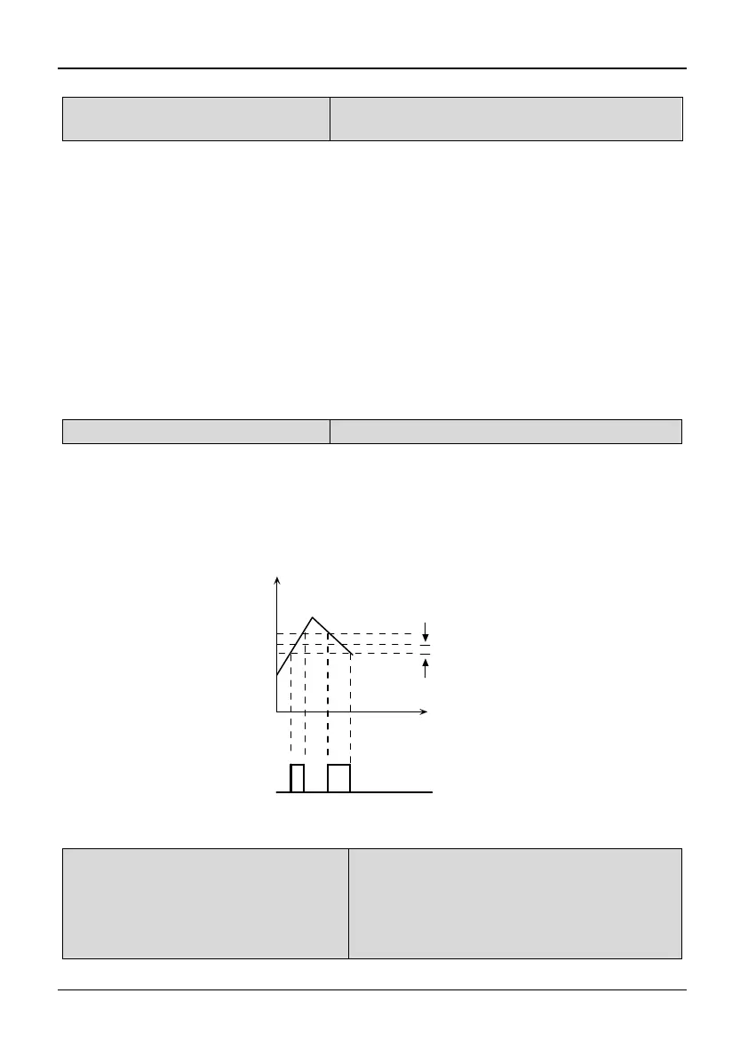
P3.18 FAR detection width
Range: 0.00~10.00Hz【2.50Hz】
Note:
◆This function used to adjust FAR detection bandwidth, when the output frequency
reaches to the reference frequency. The adjusted range is from 0 to ±10.00 Hz of
reference frequency. If the inverter’s output frequency is within the detection width of
reference frequency, a pulse signal will be output, as shown in Fig. 5-3-8.
Detection width
Time
Time
Reference
Freq.
Operating Freq.(Hz)
FAR signal
Fig. 5-3-8 FAR detection diagram
P3.19 Frequency detection
threshold (FDT level)
Range:
3004GB and below: 0.00~650.0Hz
【50.00
Hz
】
35R5GB/37R5PB and above:
0.00~400.0Hz【50.00
Hz
】