Chapter 5 Parameter Introductions
85
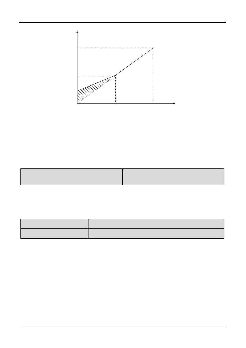
Output voltage
Output Freq.
Basic operation frequencyCut-off Freq. for torque boost
Manual
torque boost
Max output
voltage
Fig. 5-0-4 Manual torque boost diagram
(shadow area is the boost value)
Tips:
1. Wrong parameter setting can cause overheat or over-current protection of the motor.
2. When the inverter drives synchronous motor, torque boost function is recommended
to be used and V/F curve should be adjusted according to the motor parameters.
P0.20 Cut-off point used for manual
torque boost
Range: 0.00~50.00Hz
【16.67 Hz】
Note:
P0.20 defines the cut-off frequency used for manual torque boost to the basic frequency
(defined by P0.19), as shown in Fig. 5-0-4. This cut-off frequency is valid for any V/F
curve defined by P0.12.
P0.21 Acc time 1
Range: 0.1~3600s【6.0s/20.0s】
P0.22 Dec time 1
Range: 0.1~3600s【6.0s/20.0s】
Note:
Acc time: Acc time is the time taken for the inverter to accelerate from 0Hz to the
maximum frequency. Dec time is the time taken for the motor to decelerate from
maximum frequency.
This series inverter has defined 4 kinds of Acc/Dec time. Here, only Acc/Dec time
1 is defined, and Acc/Dec time 2~4 can be defined in P2.18~P2.23. You can select
different Acc/Dec time by external terminal according to your demand. In addition,
you can select different Acc/Dec time in PLC operation.