Chapter 5 Parameter Introductions
122
adjust the output gain (AO1or AO2) for the meter calibration and the change of
measuring range.
To avoid fluctuations of output in calibrating, you can make the inverter output a
standard signal (set P4.17 or P4.18 to 5 to get DC 5v. It is 50% of the full range) for
AO gain calibration. For example, to calibrate AO1, select the function code P4.22
and press “ENTER” key to enter into the function parameter menu, turn encoder on
the keyboard right
+
or left
-
to set output signal just to 5 VDC. The
modification of P4.22 is valid immediately, and would be saved into P4.22 after
pressing ENTER key. To calibrate AO2 is like the above.
If the external instrument has a great bias, the instrument should connect to the
inverter and carry out the actual adjustment.
P4.24 Max output frequency of DO
Range: Min Pulse value output of
DO~50.00kHz【10.00kHz】
P4.25 Min output frequency of DO
Range: 0.00~Max Pulse value output of
【0.00kHz】
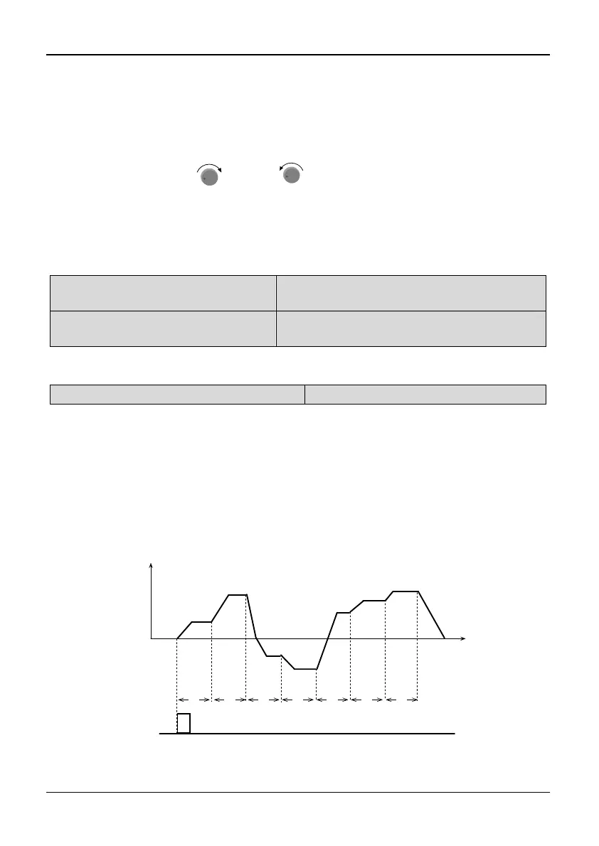
5.6 PLC Operating (Group P5)
P5.00 PLC Operating mode
Range: 0~2【2】
0: Single cycle 1 1: Single cycle 2 (holding the final
value)
2: Continuous operation
Note:
Single cycle 1
The inverter stops automatically after one cycle of operation and will start when
receiving RUN command again. As shown in Fig. 5-5-1.
T1 T2 T3 T4 T5 T6 T7
Run
command
f1
f2
f3
f4
f5
f6
f7
Operation Freq.(Hz)
Time
Fig. 5-5-1 Stop mode after single cycle of PLC