Chapter 5 Parameter Introductions
155
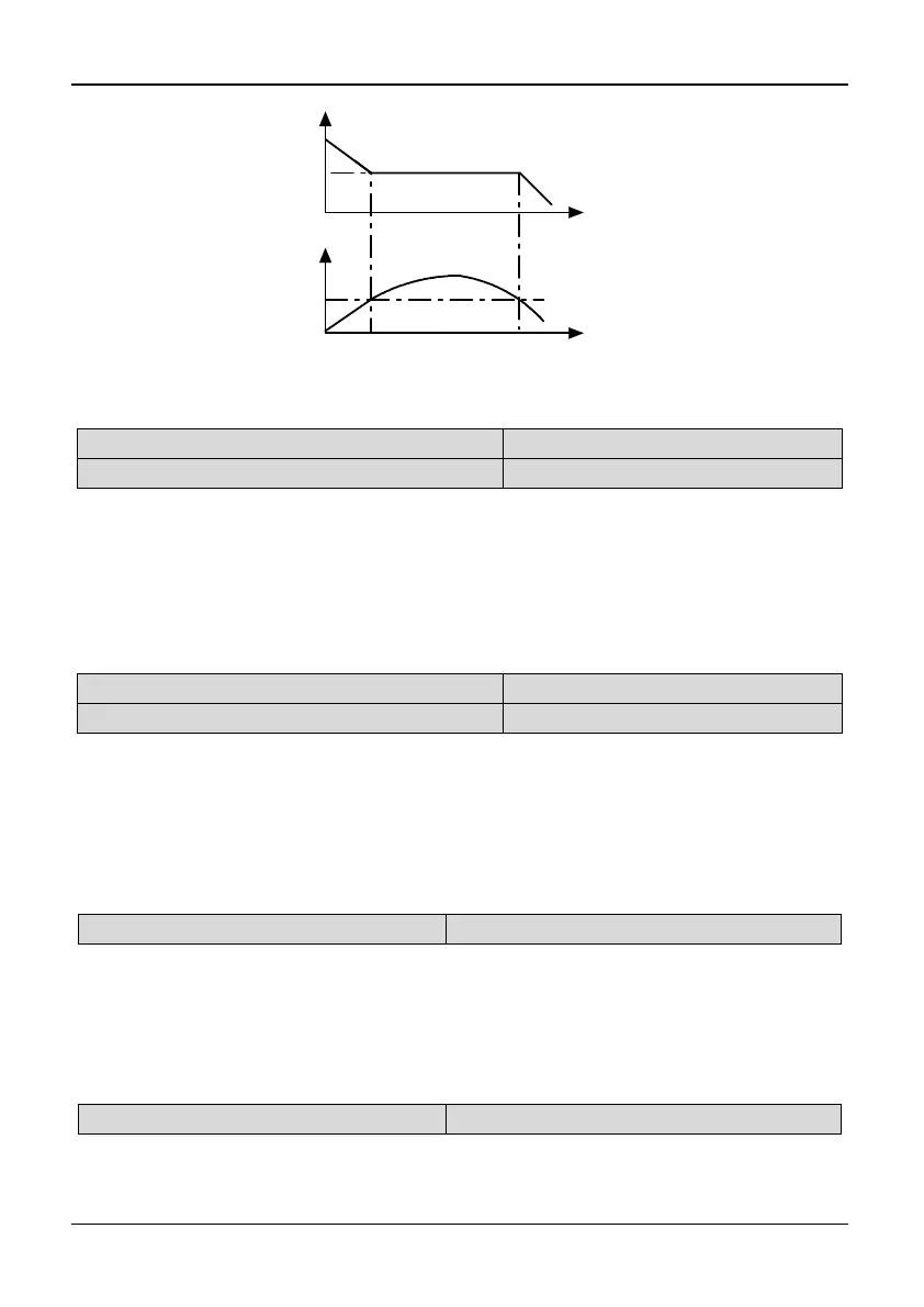
Output Freq.(Hz)
0
Time(s)
Bus voltage(%)
0
Time(s)
Deceleration
Fig. 5-13-5 Deceleration
Pd.08 Input phase loss detection level
Range:1~100%【100%】
Pd.09 Input phase loss detection delay time
Range: 2~255s【10s】
Note:
Input phase loss detection function can detect loss of input phase or a serious
imbalance in the three-phase input, in order to protect inverter. If the input phase
loss detection is hypersensitive, you can appropriately increase the detection level
(Pd.08) and detection delay time (Pd.09). Conversely, decrease the detection level
(Pd.08) and detection delay time (Pd.09).
Pd.10 Output phase loss detection level (SP0)
Range: 0~100%【2%】
Pd.11 Output phase loss detection delay time
Range: 0.0~25.0s【2.0s】
Note:
Output phase loss detect function can detect loss of output phase or a serious
imbalance in the three-phase output, in order to protect inverter and motor. If the
detection of output phase loss is hypersensitive, you can appropriately decrease the
detection level (Pd.10) and increase the detection delay time (Pd.11). Conversely,
increase the detection level (Pd.10) and decrease detection delay time (Pd.11).
Pd.12 Enabling keyboard keys UP/DN
Range: 0,1【0】
0: Invalid
1: Enabled
Note:
In the digital encoder damage cases, set Pd.12 to 1, so “JOP” key can be used as
UP and direction key can be used as DN, or press “>>+JOP” key and hold 5
minutes, then the function will be enabled.
Pd.13 AE1, AE2 Alarm choice
Range: 0,1【0】
0: Not show alarm
1: Display alarm