Chapter 5 Parameter Introductions
142
The motor power should match that of the inverter. Generally, the motor power is
allowed to be 20% lower than that of the inverter or 10% higher; otherwise, the
control performance would not be ensured.
PA.03 No load current I0
Range: 0.1~999.9A【This value depends on the
inverter model】
PA.04 Resistance of
stator %R1
Range: 0.00%~50.00%【This value depends on the
inverter model】
PA.05 Leakage
inductance %X
Range: 0.00%~50.00%【This value depends on the
inverter model】
PA.06 Resistance of
rotor %R2
Range: 0.00%~50.00%【This value depends on the
inverter model】
PA.07 Mutual
inductance %Xm
Range: 0.0%~200.0%【This value depends on the
inverter model】
Note:
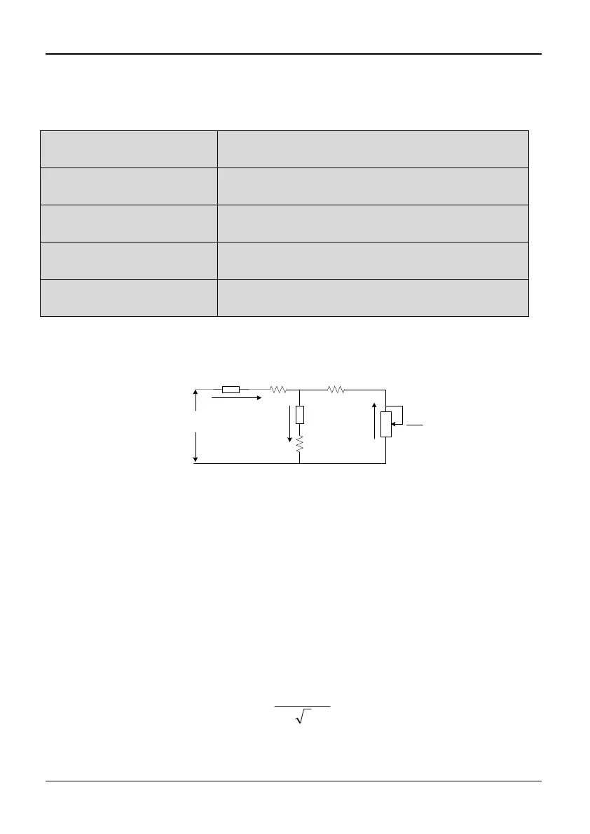
See Fig 5-10-1 for details.
1
U
1
R
1
jX
m
R
m
X
2
jX
R
2
0
I
1
I
2
I
Fig. 5-10-1 Motor equivalent circuit
In Fig. 5-10-1, R1, Xl, R2, X2, Xm, and I0 represent resistance of stator, leakage
inductance of stator, resistance of rotor, leakage inductance of rotor, mutual
inductance and current without load respectively. The setting of PA.05 is the sum
of leakage inductance of stator and leakage inductance of rotor.
The PA.04~PA.07 settings are all percentage values calculated by the following
formulas:
V: Rated voltage;
I: Motor rated current
Formula used for calculating resistance (resistance of stator or rotor)
%100
3/
%
IV
R
R
Formula used for calculating inductance (leakage inductance or mutual inductance):