Chapter6 Troubleshooting
163
Chapter 6 Troubleshooting
6.1 Troubleshooting
When the inverter has detected a fault, the keyboard will display the fault code, and the
inverter will stop PWM output and come into fault state. In the fault indicator TRIP will
flicker, the fault relay will output the programming function and the motor will coast to
stop. At this time, you should find the reason of fault and apply corrective actions. If the
listed troubleshooting cannot solve the problem, please contact our company directly.
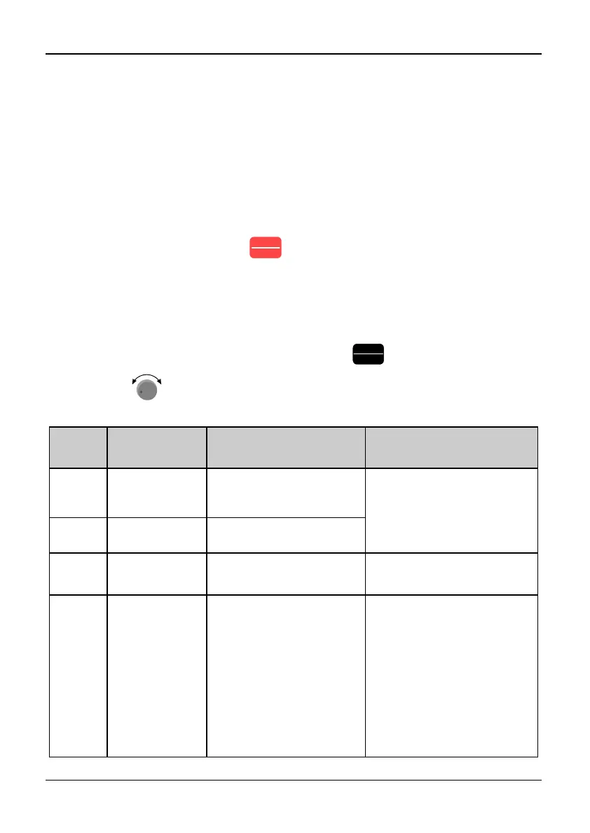
After debugging, you can press
STOP
RESET
or replace external terminals to restart the
inverter. Attention: the inverter can’t startup even through debugging has been finished if
operating signal isn’t removed, you should cut operating signal first and then close again
or remove main circuit power supply once to make the fault reset. If the SC fault
appeared, the replacement is only permitted after 10 seconds. If you want to see the work
condition (such as output frequency, reference frequency, output current, bus voltage.,
etc) or contents of the latest three fault, please press
PRG
ESC
to enter into program state
and then dial
-
+
to see parameter value of function code PE.00~PE.08.
Table 6-1 Troubleshooting
Fault
display
Name of
protection
Possible reasons of fault Actions
Uu1
Bus Under
voltage during
running.
●Abnormity input
voltage
●Check voltage of power
supply
●Check the setting of
detection level
Uu2
Control circuit
under voltage
①
●Control circuit under
voltage
Uu3
Charge circuit
abnormal
①
●MC fault ●Check charge circuit
OC1
Over current
in Acc process
●Too short accelerating
time
●Unsuitable V/F curve
●Voltage of power supply
is low
● Capacity of inverter is
too small.
●Output load of the
inverter is short
circuited
●Increase accelerate time
●Adjust the setting of V/F
curve, appropriate setting
of torque boost mode
●Check input power supply
● Select bigger capacity
inverter.
●Check resistance of the
motor’s winding; check
insulation of the motor