Chapter 2 Installation and Wiring
29
4)Use external power supply by drain connection method (Attention: be sure to
disconnect the cable JP1 between PLC and 24V for models of 3R75GB~3004GB; and
disconnect the wiring cable between PLC and 24V for models of
35R5GB/37R5PB~3500G).
.
Fig. 2-25 Drain Connection Method(in 3R75GB/31R5PB~3004GB/35R5PB only
X1~X5)
Wire Multi-Function Output Terminals
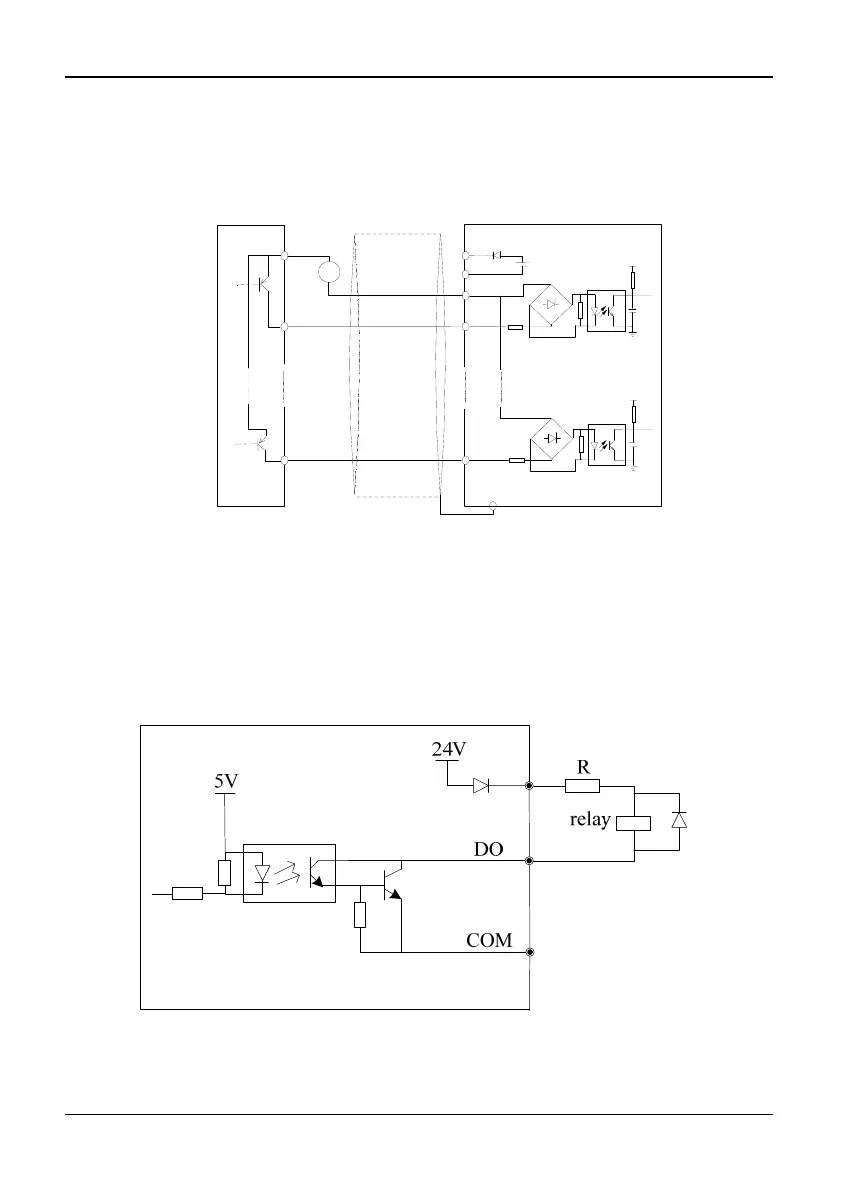
1)Multi-function output terminals D0 as switching output can use the internal 24V
power supply of inverter and the wiring method is shown in Figure 2-26.
Fig. 2-26 Wiring method 1 of DO as switching output
20~30V
PE
1
PLC
X1
24V
COM
24V DC
+
5V
8
X8
5V
External controller
Shield wire near grounding