Chapter 5 Parameter Introductions
149
when the user press shift key >> to monitor this object or Analog PID feedback,
analog PID feed can be adjusted online and be saved into P7.02 after press
“ENTER” key.
PC.17 External counting value (no unit)
Range: 0,1【0】
0: No display 1: Display
Note:
If PC.17 is set to 1, external count value will be displayed in monitoring state, and
all unit indicators will be off. If it is set to 0, external count value will not be
displayed.
PC.18 Terminal status (no unit)
Range: 0,1【0】
0: No display 1: Display
Note:
If PC.18 is set to 1, the terminal status will be displayed in monitoring state; If
PC.18 is set to 0, the terminal status will not be displayed.
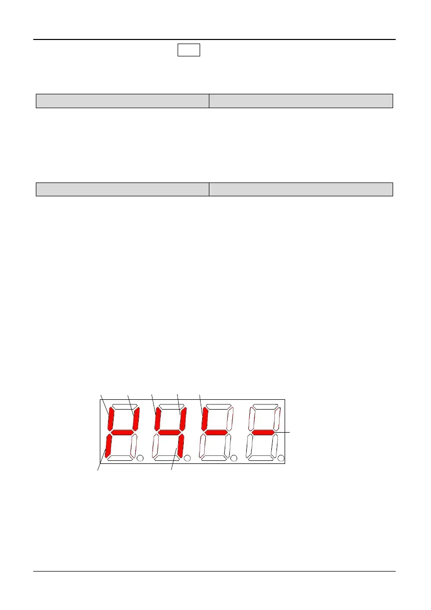
Model of 3004GB/35R5PB and the below models: The terminal information
includes status of terminal X1~X5, D0 and relay output terminal TA. The status of
terminals is indicated by "on" or "off" of the segment. The segment will turn on if
the terminal is valid. The segment will turn off if the terminal is invalid. The central
four segments are always on for the convenience of observation. As shown in
Fig.5-12-1:
Model of 35R5GB/37R5PB and above models: The terminal information includes
status of terminal X1~X8, bi-direction open-collector output terminals D0, Y1 and
Y2, and relay output terminal TA and BRA. The status of terminals is indicated by
“on” or “off’ of the segment. The segment will turn on if the terminal is valid. The
segment will turn off if the terminal is invalid. The central four segments are always
on for the convenience of observation. As shown in Fig.5-12-2:
X3
X5
X4
X2
X1
Relay
TA/TB/TC
DO
Always on
Fig. 5-12-1 Terminal status diagram of S2R4GB~3004GB/35R5PB