Chapter 8 Maintenance
181
M
D
O
GND
F
(
-
)
(
+
)
U
V
WT
S
R
A
A
A
V
V
V
W
W
V
V
V
A
AA
W
W
V
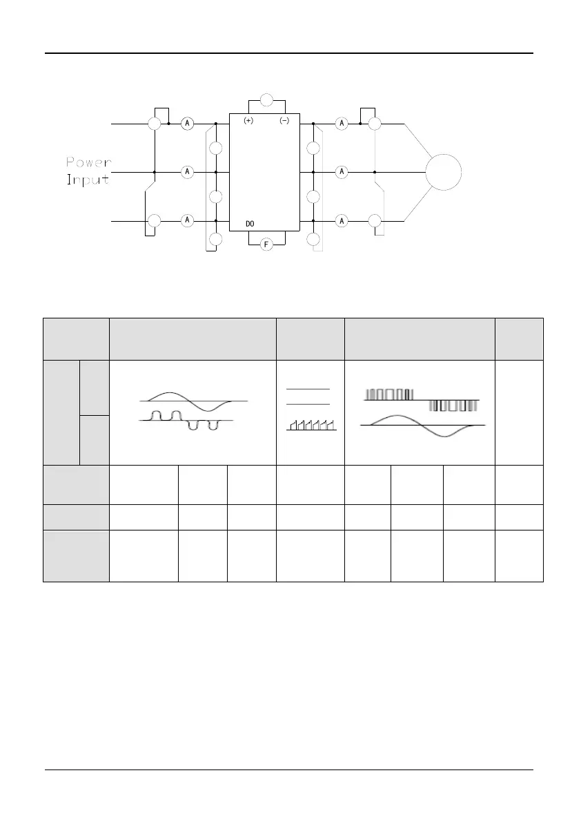
Fig. 8-1 Recommendable Wiring of Main Circuit Electro Measurement
Table 8-3 Description of Main Circuit Electro Measurement
Item
Input
(Power supply)
DC
Intermediate
Link
Output
(Motor)
D0
terminals
Wave form
Voltage
Current
Measuring
instrument
Voltmeter
Current
meter
Power
meter
DC
voltmeter
Volt
meter
Current
meter
Power
meter
Volt
meter
Instrument
Type
Moving-coil
Electro-
Magnetic
Electro-
dynamic
Magneto-
Electric
Rectifier
-type
Electro-
Magnetic
Electro-
dynamic
Magneto-
Electric
Parameter
Virtual
value of
First
harmonic
Total
virtual
value
Total
virtual
power
DC
voltage
Virtual
value of
First
harmonic
Total
virtual
value
Total
virtual
value of
power
DC
voltage
When power supply is asymmetric seriously or three phases current is not balanced,
please use electro-dynamic type three-phase wattmeter to measure the power.
Because the product has passed electric insulation test and dielectric strength
examination, similar experiment is not required. In addition, the experiment will
decrease the insulating voltage proof and improper experiment may cause product failure.
If the experiment must be done, only skilled workers satisfy the qualification.
When doing experiment of main circuit voltage proof, please choose capacity equivalent
instrument, using time and leakage current of which can be set. Moreover, this
experiment will shorten life span of the device. Also, the main circuit terminals ( R, S, T,