Chapter 5 Parameter Introductions
94
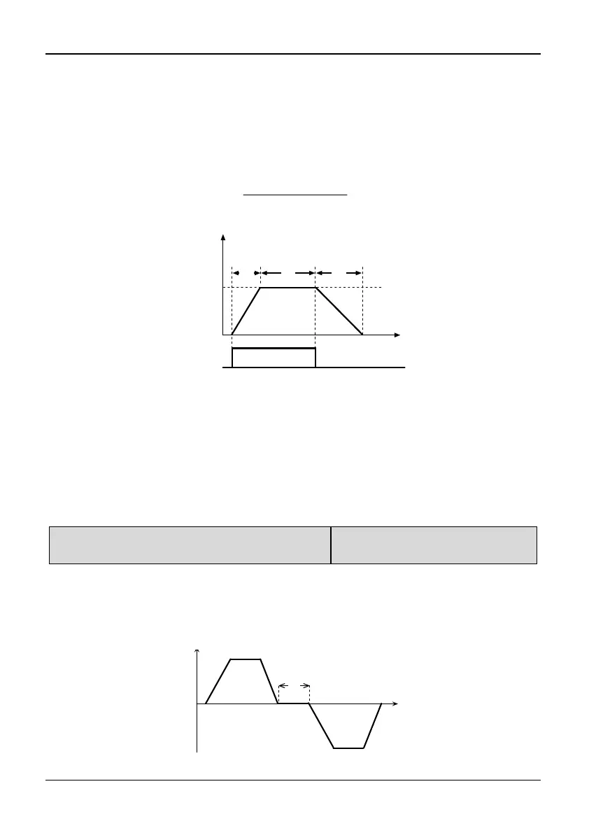
As shown in Fig. 5-2-1, t
1
is Acc time of Jog and t
3
is Dec time of Jog t
2
is the Jog
time; P2.00 is the Jog frequency.
Actual Acc time of JOG (t
1
) can be determined by the following formula. So does
the actual Dec time of JOG (t
3
).
JOG stop mode depends on the value of P2.02: If P2.02 setting is not 0, the motor
will stop as
stop mode 0; if P2.02 setting is 0, the motor will coast to stop.
Operation Freq.(Hz)
P2.00
JOG Command
Time
t
2
t
1
t
3
t
1
=
P2.00×
P2.01
P0.07
Fig. 5-2-1 JOG Running
Tips:
1. In Jog operation, the inverter starts according to starting mode 0. The unit of
Acc/Dec time is second.
2. If deceleration time of Jog is 0: coast-to-stop, but DC injection braking terminal
takes effect when stop Jog operation, the deceleration time will be P2.23 Dec time 4.
3. Jog operation can be controlled by keyboard, terminals or serial port.
P2.03 Switching time between run forward and
reverse
Range: 0.0~3600s【0.0s】
Note:
The delay time is the transition time at zero frequency when the inverter switches its
running direction as shown in Fig. 5-2-2 as t
1
1
.
Operation Freq.(Hz)
Time
t1
Fig. 5-2-2 FWD/REV switching time diagram