Chapter 5 Parameter Introductions
150
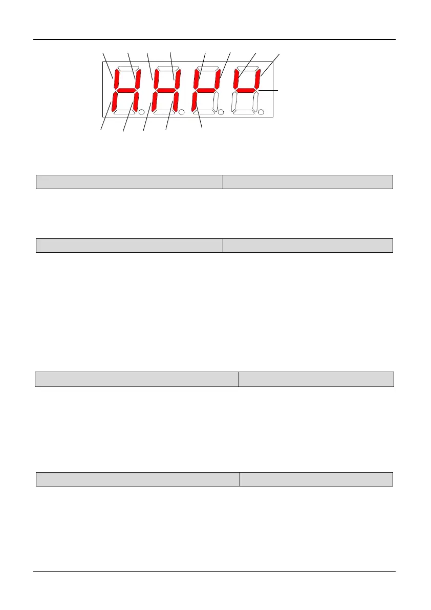
X3 X5 X7 X8X6X4X2X1
Y1 Relay1
TA/TB/TC
Relay2
BRA/BRB/BRC
Y2DO
Always on
Fig. 5-12-2Terminal status diagram of 35R5GB/37R5PB~3500G
PC.19 Actual length (m)
Range: 0,1【0】
0: No display 1: Display
Note:
If PC.19 is set to 1, the actual length will be displayed in monitoring state, and all
unit indicators will be off. If it is set to 0, actual length will not be displayed.
PC.20 Power on display
Range: 1~19【1】
PC.20 is used to set the first display parameter at power on. The setting value is from
1 to 19, corresponding to PC.01~PC.19 respectively. If the display property of the
first display parameter is 0 (PC. XX=0, XX is the value of PC.20), the keyboard will
search from the current settings of PC.20 (PC. XX) to the last (PC.19) and then back
to go on search from 1 (PC.01) to the value of PC.20, until the setting value is 1. In
addition, keep this display object as the first monitoring object.
Power on display selection will take a priority display of PC.01 ~ PC.19 absolutely;
and only takes affect at the boot time. When there is an error, an alarm or a
communication CALL to be displayed, the error will display at first, then the alarm or
the CALL, and the power on display selection will not work.
PC.21 Rotating speed display coefficient
Range: 0.1~999.9%【100.0%】
Note:
PC.21 (Rotating Speed display coefficient) is used to correct the bias of displayed
rotating speed and it has no influence on actual speed.
Rotate speed = actual rotate speed × PC.21 (PG)
Rotate speed=120 × Operating Frequency ÷ PA.00 × PC.21 (non-PG)
Reference speed= PID reference speed × PC.21 (PG)
Reference speed=120*reference frequency÷PA.00×PC.21 (non-PG)
PC.22 Linear speed display coefficient
Range: 0.1~999.9%【100.0%】
Note:
PC.22 (Linear speed coefficient) is used to correct the bias of displayed line speed
and it has no influence on actual speed.
Linear speed = Running frequency × PC.22 (non PG)
Linear speed = rotate speed × PC.22 (PG)
Reference linear speed= reference frequency* PC.22 (non PG)