Chapter 2 Installation and Wiring
27
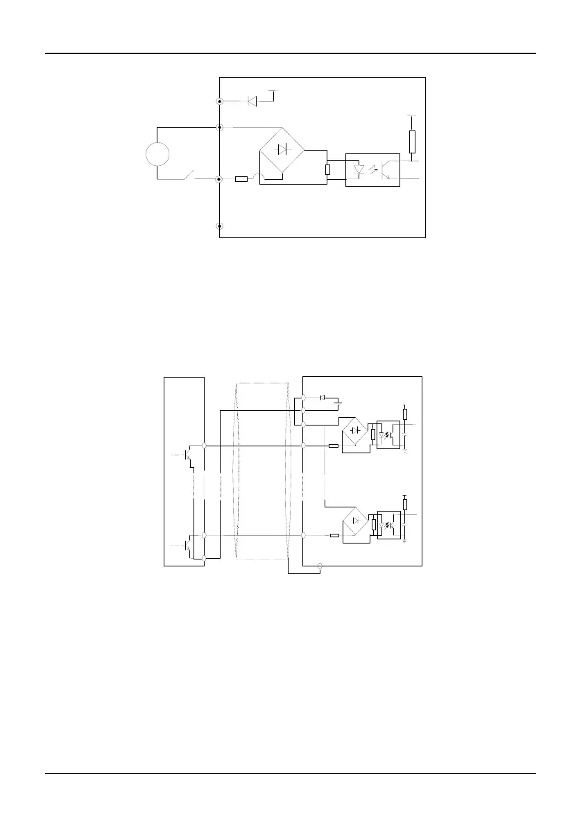
Fig. 2-21 Use an external supply(in 3R75GB/31R5PB~3004GB/35R5PB only
X1~X5)
Method 2 of Connections
1)Inverter’s internal +24V power supply is used and the external controller uses NPN
transistors whose common emitters are connected, as shown in Figure 2-22.
Fig. 2-22 Source connection method by using inverter's internal +24 V power
supply (in 3R75GB/31R5PB~3004GB/35R5PB only X1~X5)
2)Inverter’s internal +24 V power supply is used and the external controller uses NPN
transistors whose common emitters are connected, as shown in Figure 2-23
(Attention: be sure to disconnect the cable JP1 between PLC and 24V for models of
3R75GB~3004GB, and disconnect the wiring cable between PLC and 24V for
models of 35R5GB/37R5PB~3500G, short circuit terminal PLC and COM).
COM
PE
1
PLC
X1
24V
COM
24V DC
5V
8
X8
5V
External
Shield wire near grounding
+24V
X1~X8
PLC
5V
COM
R
DC
K
+