Chapter 2 Installation and Wiring
31
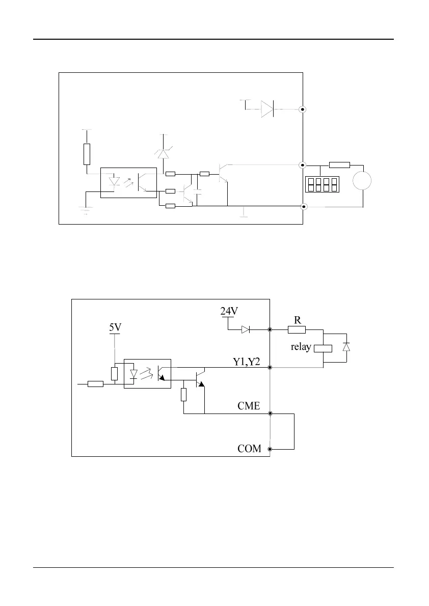
4)Multi-function output terminals / Pulse output terminal DO as Pulse output can also
use the external 9~30V power supply and the wiring is shown in Figure 2-29.
Fig. 2-29 Wiring method 2 of DO as pulse output
5)Multi-function output terminals Y1 and Y2 can use the internal 24V power supply of
inverter and the wiring method is shown in Figure 2-30.
Fig. 2-30 Wiring method 1 of multi-function output terminal
(only 35R5GB/37R5PB~3500G)
+24V
24V
4.7K
DO
COM
+5V
+24V
20~30V
+-
Digital
fr
n
m