Chapter 4 Parameter Index
67
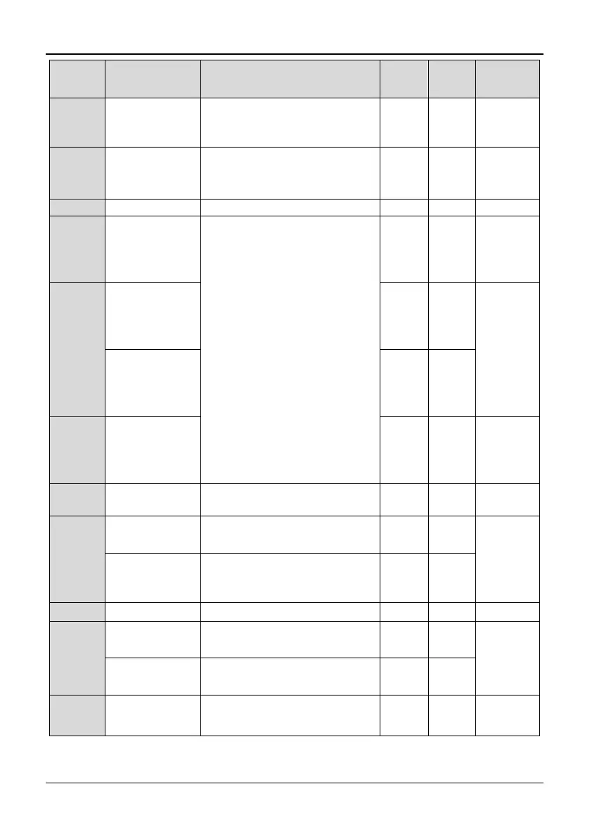
Function
code
Function Name Range of settings Default Change
MODBUS
Address
P4.14
Physical value 3
corresponding to
Max pulse value
Input
0.0~100.0% 100.0% ○ 050E
P4.15
Pulse input filter
time constant 3
(pulse Input
Terminal)
0.01~50.00s 0.05s ○ 050F
P4.16 PG Pulse Range 1~9999 1024 ○ 0510
P4.17
AO1 function
definition
0: Output frequency before
compensation (0~ Maximum
Frequency)
1: Output current (0~2* inverter rated
current)
2: Output voltage (0~Maximum
Voltage)
3: PID feed (0~10V)
4: PID feedback (0~10V)
5: Adjust signals (5V)
6: Output torque (0~2*inverter rated
torque)
7: Output power (0~2*Inverter rated
power)
8: Bus voltage (0~1000V)
9: AI1 (0~10V)
10: AI2 (0~10V/0~20mA)
11: Output frequency after
compensation (0~Maximum
Frequency)
12~14: Reserved
15: NULL
0 × 0511
P4.18
Reserved
(3004GB/35R5PB
or below)
0 -
0512
AO2 function
definition
(35R5GB/37R5PB
and above)
1 ×
P4.19 DO output 15 × 0513
P4.20
AO1 output range
selection
0: 0~10V/0~20mA
1: 2~10V/4~20mA
0 ○ 0514
P4.21
Reserved
(3004GB/ 35R5PB
or below)
Reserved 0 -
0515
AO2 output range
selection(35R5GB
/37R5PB and
above)
0: 0~10V/0~20mA
1: 2~10V/4~20mA
0 ○
P4.22 Gain of AO1 1~200% 100% ○ 0516
P4.23
Reserved
(3004GB/ 35R5PB
or below)
Reserved 0 -
0517
Gain of AO2
(35R5GB/37R5PB
and above)
1~200% 100% ○
P4.24
Max output
impulse frequency
of DO
Min Pulse frequency output of
DO~50.00kHz
10.00kH
z
○ 0518