10Memory Interface
10 – 27
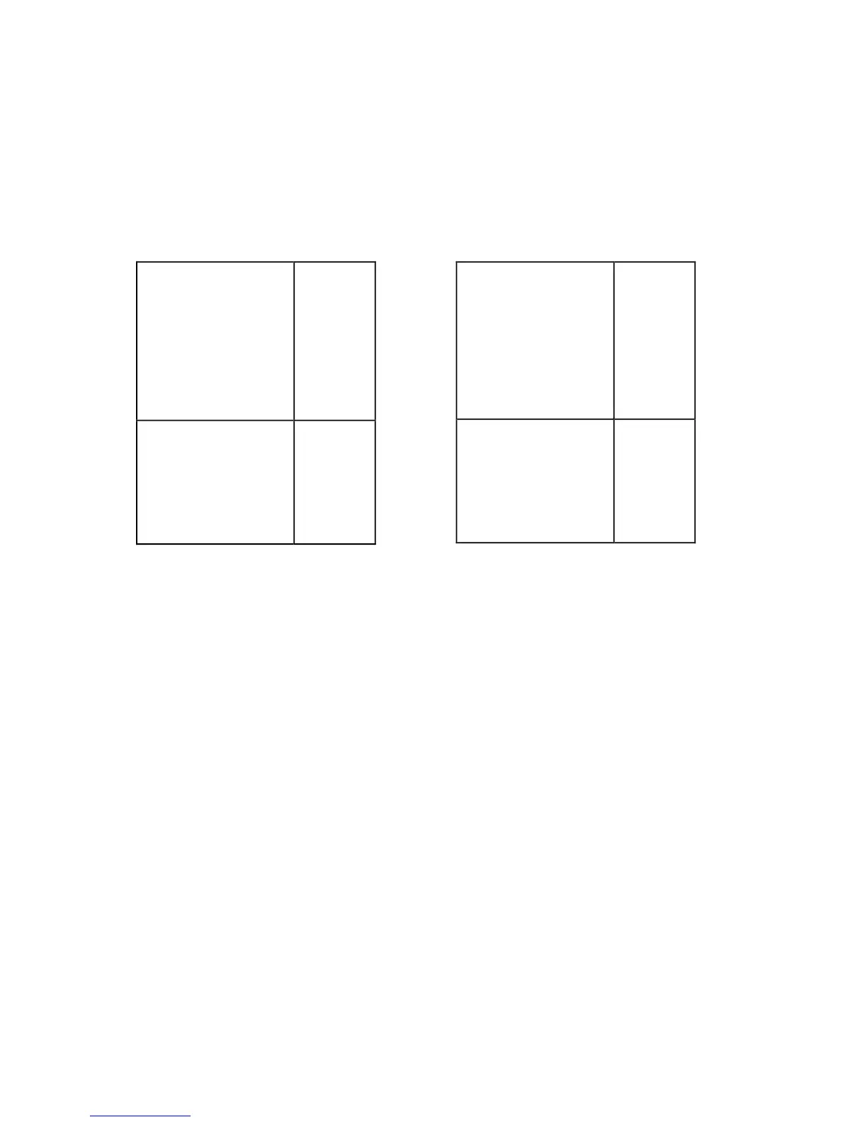
Program Memory Address
8K Internal
(PMOVLAY = 0)
or
External 8K
(PMOVLAY = 1 or 2)
0x3FFF
0x2000
8K Internal
0x1FFF
0x0000
Program Memory Address
8K Internal
(PMOVLAY = 0)
0x3FFF
0x2000
8K External
0x1FFF
0x0000
MMAP = 0 MMAP = 1
Figure 10.25 ADSP-2181 Program Memory Map
The following example instructions demonstrate how to use the
PMOVLAY register.
PMOVLAY=DM(0x1234); {type 3 instruction, PMOVLAY is loaded
}
{ with the contents of address
DM(0x1234)}
PMOVLAY=2; {type 7 instruction, PMOVLAY is loaded }
{ with the value 2. }
PMOVLAY=AX0; {PMOVLAY is loaded from AX0 register.}
AX0=PMOVLAY; {AX0 is loaded from PMOVLAY register.}
If you are using a system design that sets MMAP=1, note that the first 8K is
used to support a single segment of external memory. This allows an
external ROM-based system to operate properly. In this mode, the external
program memory address always has A13 set to 0 and 8K of internal PM is
available. Set PMOVLAY=0 and MMAP=1. This mode is available on other

 Loading...

