2-10 Test Panel Connectors Chapter 2 — Quick Start Guide
2-12 MS20xxA VNA Master UG 10580-00166 Rev. C
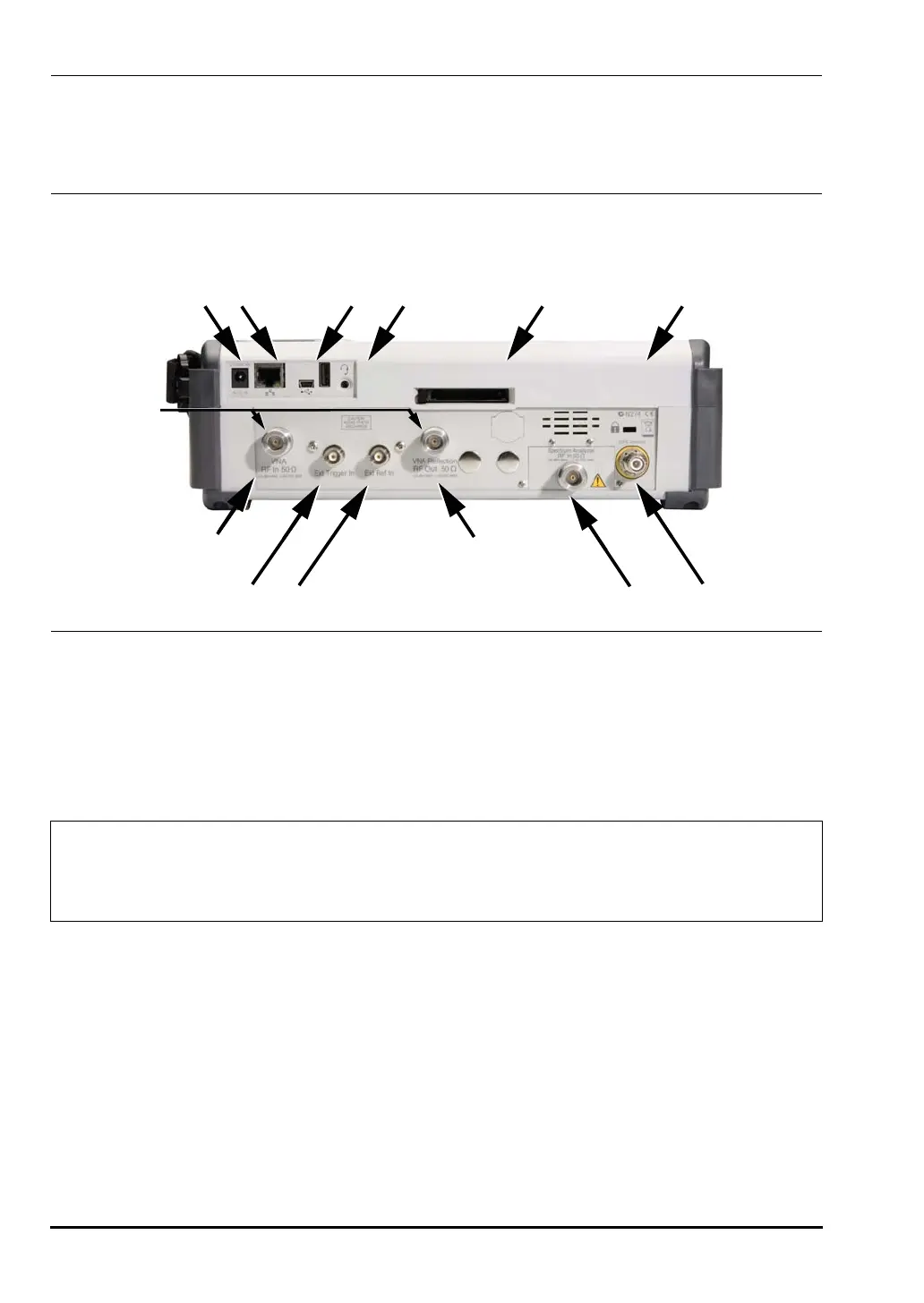
MS203xA Test Panel Connectors
The connectors and indicators located on the test panel of the MS203xA are shown in
Figure 2-10 and are described below.
External Power
The external power connector is used to power the unit and for battery charging. Input is 12
to 15 VDC at up to 5.0 A. A green flashing indicator light near the power switch shows that
the instrument battery is being charged by the external charging unit. The indicator is
steadily illuminated when the battery is fully charged.
LAN Connection
The RJ-45 connector is used to connect the VNA Master to a local area network. Integrated
into this connector are two LEDs. The amber LED indicates the presence of LAN voltages–a
live LAN connection–while the green LED flashes to show that LAN traffic is present. The
instrument IP address is set by pressing the
Shift key, then the System (8) key followed by the
System Options soft key and the Ethernet Config soft key. The instrument Ethernet address can
be set automatically using DHCP, or manually by entering the desired IP address, gateway
address, and subnet mask.
Figure 2-10. MS2034A and MS2036A Test Panel Connectors
Warning
When using the AC-DC Adapter, always use a three-wire power cable connected
to a three-wire power line outlet. If power is supplied without grounding the
equipment in this manner, then the user is at risk of receiving a severe or fatal
electric shock.
MS2034A and MS2036A Test Panel Connections
External
Power
LAN
Connection
USB
Interface
Headset
Jack
Compact
Flash Socket
Fan
Exhaust Port
VNA RF In
50 Ohm
External
Trigger In
VNA Reflector/RF
Out 50 Ohm
Vector
Network
Analyzer
Connectors
External
Reference In
Spectrum Analyzer
RF In 50 Ohm
GPS
Antenna
10580-00166C.book Page 12 Thursday, February 21, 2008 12:52 PM