3-6 VNA Measurements - 2-Port Phase Measurement Chapter 3 — Vector Network Analyzer
3-22 MS20xxA VNA Master UG 10580-00166 Rev. C
2-Port Phase Measurement
The following example compares the phase of two cables using a 2-port phase measurement.
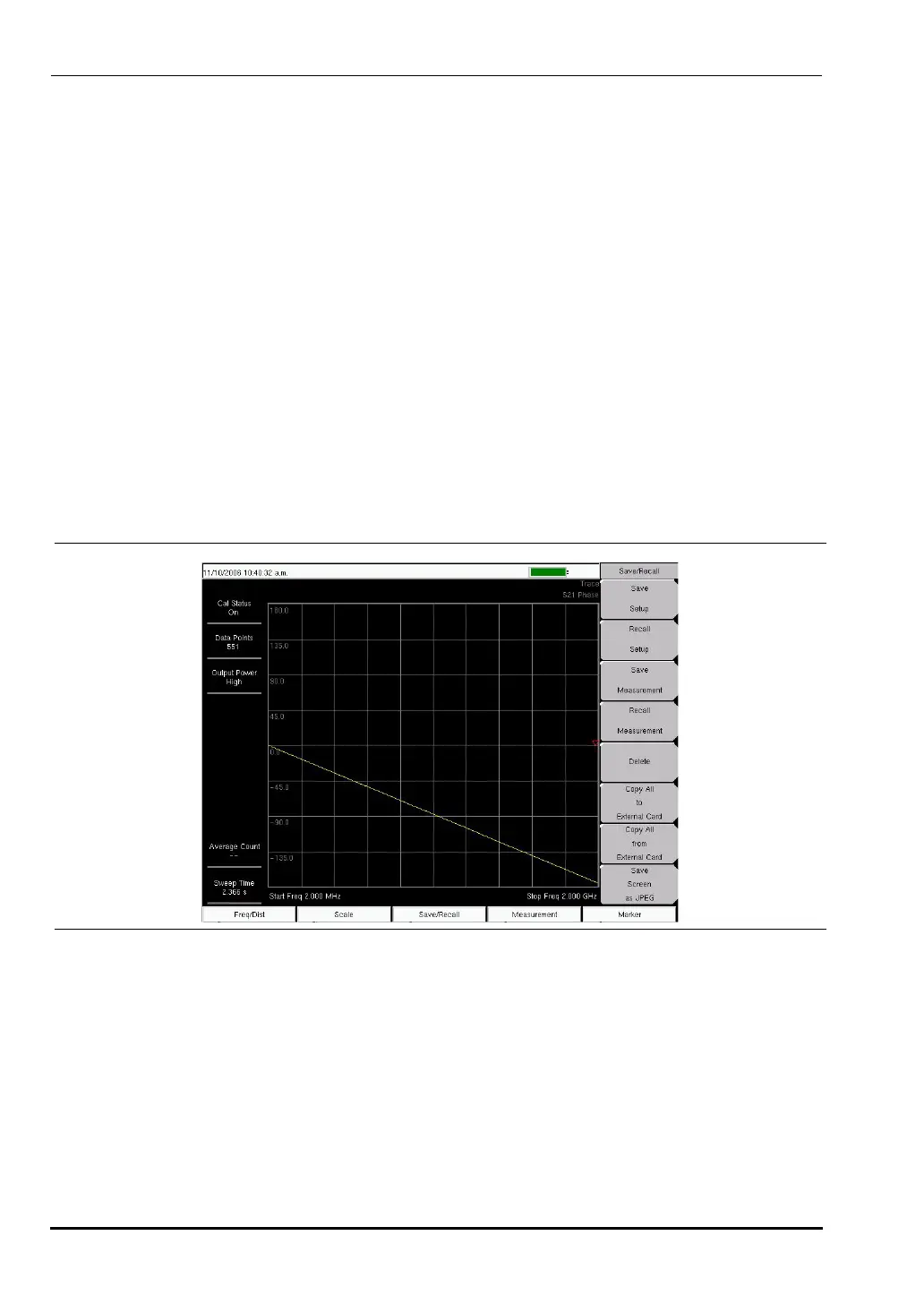
Figure 3-15 shows an S21 Phase measurement (using the VNA measurement menu).
Procedure
1. Press the Measurement function hard key and select Next | 1-Port Phase (Field menu) or
S11 Reflection | Phase (VNA menu).
2. Press the
Freq/Dist function hard key and set the Start Frequency and Stop Frequency.
3. Press the
Start Cal soft key and perform a 2-port calibration at the end of a phase stable
cable.
4. Connect Cable A (the reference cable) between the
RF Out and RF In connectors.
5. Press the
Shift key, then the Trace (5) key.
6. Select the
Copy Trace to Display Memory soft key.
7. Remove Cable A and connect Cable B (the cable under evaluation).
8. Select the
Trace Minus Memory soft key to view the difference in phase between the two
cables.
Smith Chart
The VNA Master can display 1-port measurements in a standard Normalized 50 Ohm or 75
Ohm Smith Chart. When markers are used, the real and imaginary components of the Smith
Chart value are displayed.
Anritsu Master Software Tools includes more options and a calculator that can easily show
the values of the return loss, VSWR, or reflection coefficient of a specific Smith Chart.
Limit Lines in a Smith Chart will appear as circles (constant reflection coefficient) and can be
entered in VSWR units.
Figure 3-15. S21 Phase Measurement (VNA Measurement Menu Shown)
10580-00166C.book Page 22 Thursday, February 21, 2008 12:52 PM