Chapter 3 — Vector Network Analyzer 3-5 Using Limit Lines - Setting up Segmented Limit Lines
MS20xxA VNA Master UG 10580-00166 Rev. C 3-11
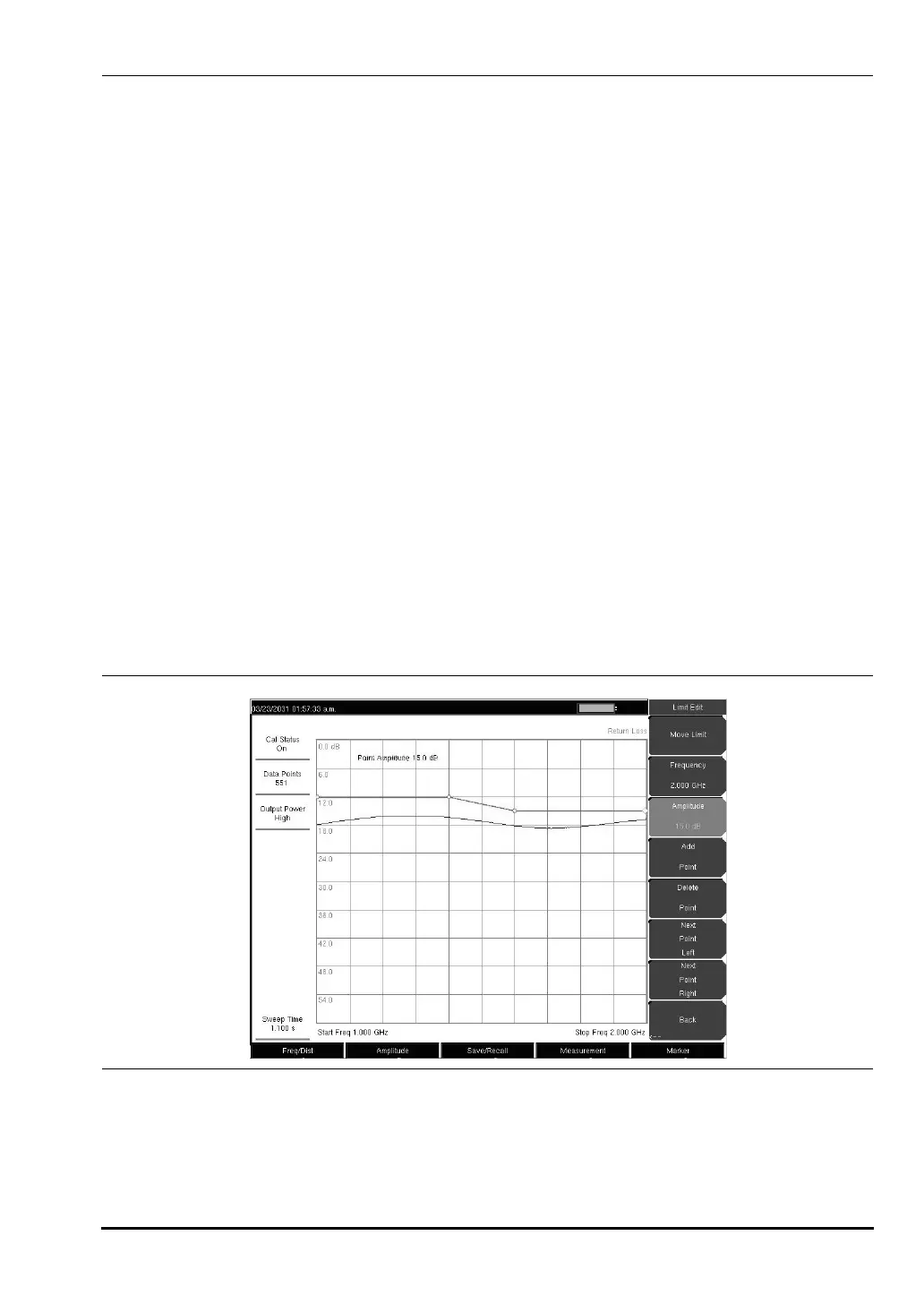
Setting up Segmented Limit Lines
Segmented Limit Lines can be useful if there are different specifications for different
frequency ranges. The following procedure creates segmented Limit Lines for a Return Loss
Measurement. Limits are set to 12 dB between 1000 MHz and 1400 MHz and 15 dB between
1600 MHz and 2000 MHz.
1. Press the
Shift key, then the Limit (6) key.
2. Press the
On/Off soft key to turn on the upper or lower limit line.
3. Press the
Limit Edit soft key.
4. Press the
Move Limit soft key and use the number keys to enter a limit value of 12 dB.
The limit value can also be moved using the up and down arrow keys or the rotary
knob.
5. Press the
Frequency soft key and use the number keys to enter 1000 MHz.
6. Press the
Add Point soft key.
7. Press the
Frequency soft key and use the number keys to enter 1400 MHz.
8. Press the
Add Point soft key.
9. Press the
Frequency soft key and use the number keys to enter 1600 MHz.
10. Press the
Point Value soft key and use the number keys to enter 15 dB.
11. Press the
Next Point Right soft key to select the limit point at the far right of the display.
12. Press the
Frequency soft key and use the number keys to enter 2000 MHz.
13. Press the
Point Value soft key and use the number keys to enter 15 dB.
Figure 3-5. Segmented Limit Lines
10580-00166C.book Page 11 Thursday, February 21, 2008 12:52 PM