3-6 VNA Measurements - 2-Port Gain Measurements Chapter 3 — Vector Network Analyzer
3-20 MS20xxA VNA Master UG 10580-00166 Rev. C
8. When the Calibration is finished, Cal Status On should be displayed in the upper left part
of the display, and the trace should be a flat trace at 0 dB.
9. Connect an attenuator between the test port extension cable and the
RF In port.
Example 2
This example describes a Gain measurement of a TMA (Tower Mounted Amplifier) using the
built-in bias tee (Option 10). Figure 3-14 shows the Field measurement menu in use.
Procedure
1. Press the Measurement function hard key and select S21 Transmission | Log Magnitude (VNA
menu) or
2-Port Gain (Field menu).
2. Press the
Freq/Dist function hard key and set the Start Frequency and Stop Frequency.
3. Connect test port extension cables to the
RF Out port and the RF In port.
4. Press the
Shift key, then the Sweep (3) key.
5. Select the
Power soft key and set power to Low.
6. Press the
Start Cal soft key and perform a 2-port OSL calibration at the end of the
extension cables.
7. Connect the
RF Out cable to the ANT port of the TMA.
8. Connect the
RF In cable to RX port of the TMA.
9. Press the
Shift key, then the Sweep (3) key.
10. Select the
Bias Tee soft key and enter the appropriate voltage for the amplifier. Note that
the voltage will be applied to the center conductor of the
RF In port.
11. Turn on the Bias Tee by pressing the
Bias Tee On/Off soft key.
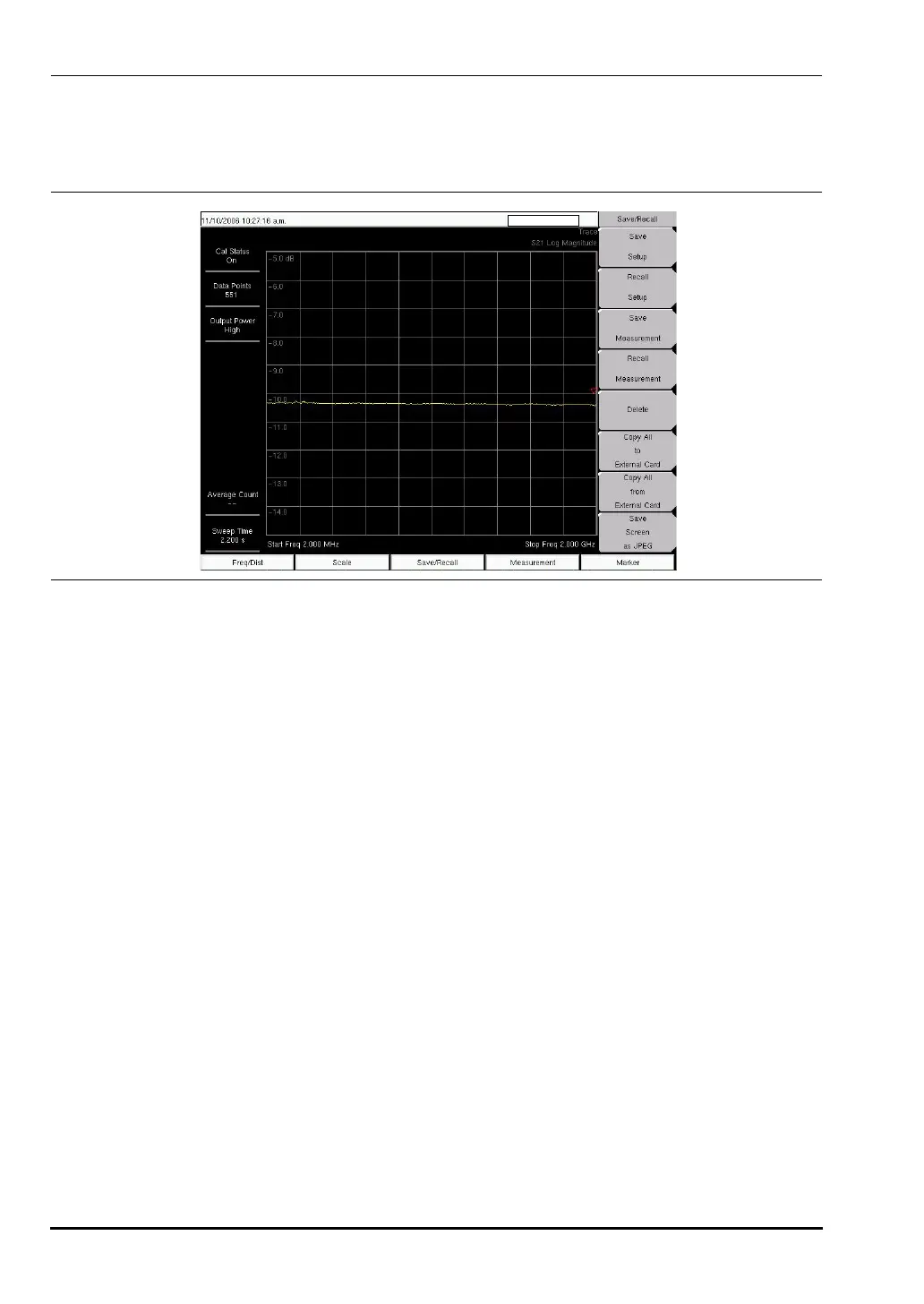
Figure 3-13. S21 Log Magnitude Measurement (VNA Measurement Menu Shown)
10580-00166C.book Page 20 Thursday, February 21, 2008 12:52 PM