2-2 Cable and Antenna Measurement Setup Cable and Antenna Analyzer
2-8 PN: 10580-00241 Rev. B Cable & Antenna Analyzer MG
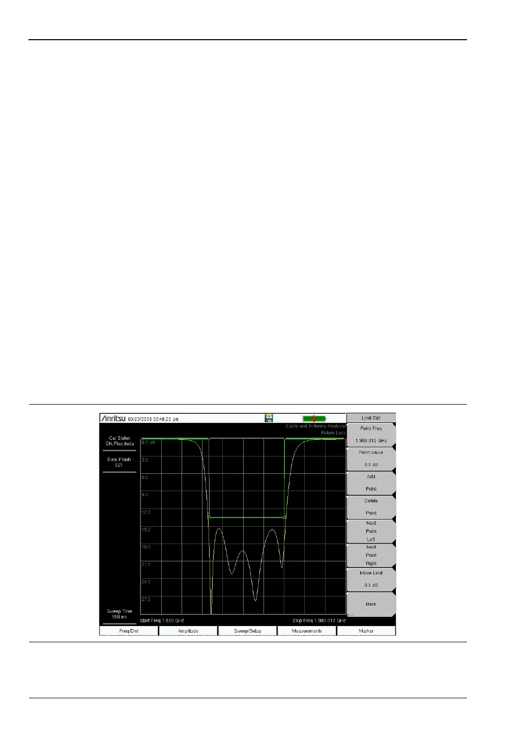
Segmented Limit Lines
The following procedure creates limit lines for a Return Loss Measurement. Limits are set to:
• 0 dB between 1800 MHz and 1830 MHz
• 13.5 dB between 1830 and 1870 MHz, and
• 0 dB between 1870 and 1900 MHz.
The frequency is set from 1800 MHz to 1900 MHz.
1. Press Shift and then Limit (6) to enter the Limit menu.
2. Press the Multi-Segment Edit key.
3. The default limit line has two points. In this example, 3 segments require 6 points.
Press the Add Point key four times to add four more points.
4. Press Next Point Left until the highlighted red point is the first point to the left. Press
Point Value and enter 0 dB.
5. Press Next Point Right and set the Point Value to 0 dB for the second point from the left.
Press Point Freq and enter 1830 MHz.
6. Press Next Point Right and set the Point Value to 13.5 dB for the third point from the left.
Press Point Freq and enter 1830 MHz.
7. Press Next Point Right and set the Point Value to 13.5 dB for the fourth point from the
left. Press Point Freq and enter 1870 MHz.
8. Press Next Point Right and set the Point Value to 0 dB for the fifth point from the left.
Press Point Freq and enter 1870 MHz.
9. Press Next Point Right and set the Point Value to 0 dB for the sixth point from the left.
Press Point Freq and enter 1900 MHz
.
Figure 2-4. Segmented Limit Lines