2-5 Cable and Antenna Measurements Overview Cable and Antenna Analyzer
2-14 PN: 10580-00241 Rev. B Cable & Antenna Analyzer MG
2-5 Cable and Antenna Measurements Overview
Line Sweep Fundamentals
In wireless communication, the transmit and receive antennas are connected to the radio
through a transmission line. This transmission line is usually a coaxial cable or waveguide.
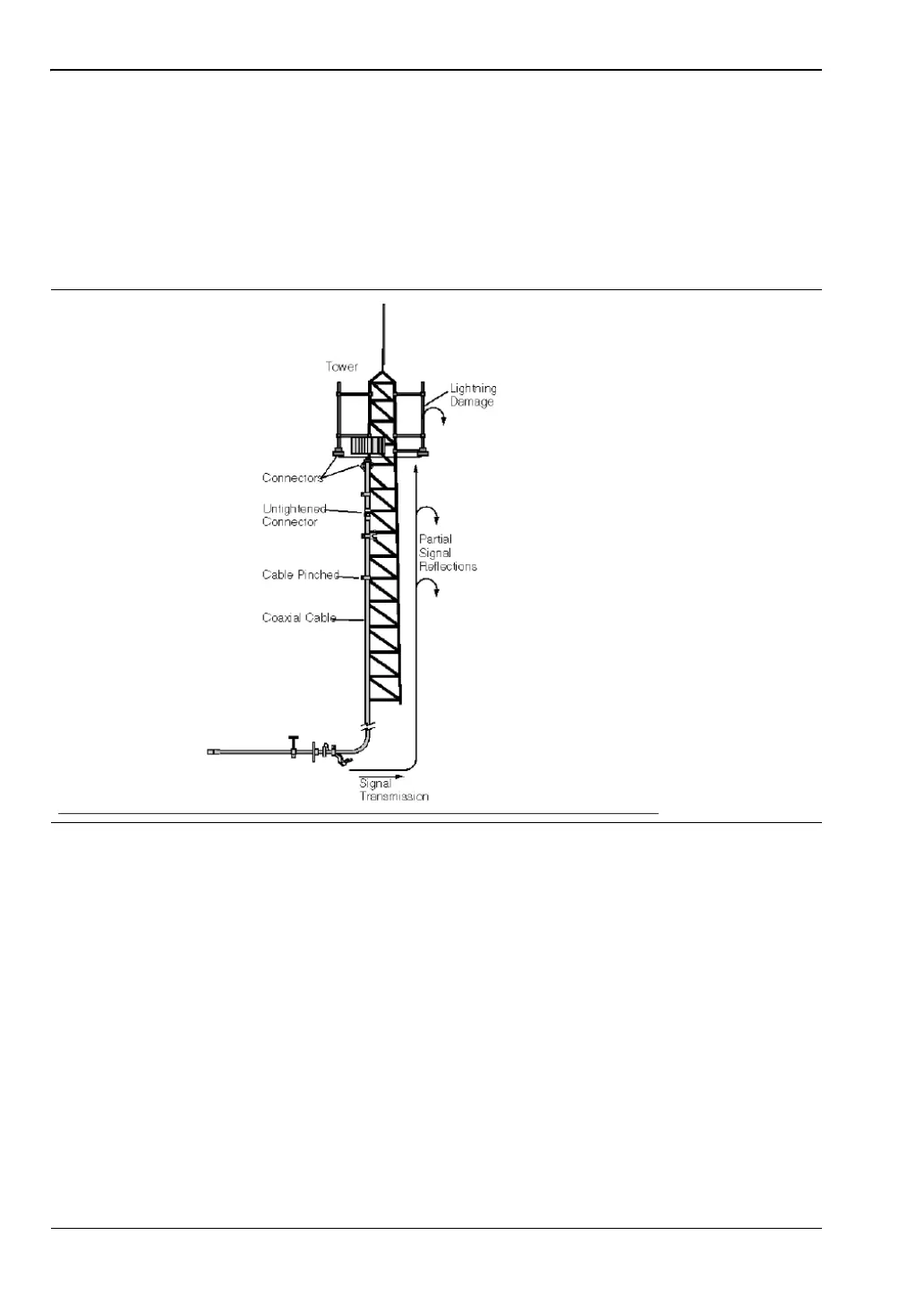
This connection system is referred to as a transmission feed line system. Figure 2-10 shows
an example of a typical transmission feed line system.
The performance of a transmission feed line system may be affected by excessive signal
reflection and cable loss. Signal reflection occurs when the RF signal reflects back due to an
impedance mismatch or change in impedance caused by excessive kinking or bending of the
transmission line. Cable loss is caused by attenuation of the signal as it passes through the
transmission line and connectors. To verify the performance of the transmission feed line
system and analyze these problems, three types of line sweeps are required:
• Return Loss
• Cable Loss, and
• Distance-To-Fault.
The measurements for these sweeps are defined as
• Return Loss - System Sweep,
• DTF - Load Sweep, and
• Cable Loss Sweep.
Figure 2-10. A Typical Transmission Feedline System