Cable and Antenna Analyzer 2-8 Cable and Antenna Analyzer Menus
Cable & Antenna Analyzer MG PN: 10580-00241 Rev. B 2-25
2-8 Cable and Antenna Analyzer Menus
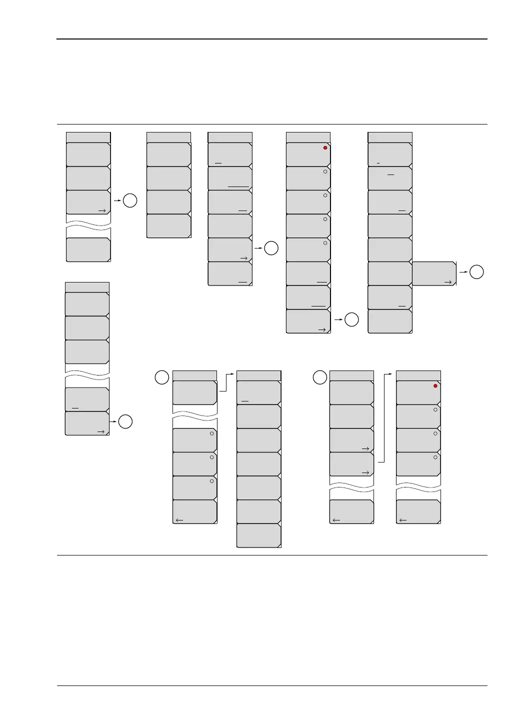
Figure 2-19 and Figure 2-20 show the map of the Cable and Antenna Analyzer menus. The
following sections describe main menus and associated submenus. The submenus are listed in
the order they appear on the display from top to bottom under each main menu.
Figure 2-19. Menu Keys (1 of 2)
Amplitude
Measurement 1/2
Bottom
-120.0 dB
To p
100.0 dB
B
C
D
E
More
Cable
Windowing
More
Marker
Options
Autoscale
Data Points
275
Fullscale
Freq
Start Freq
10.000 MHz
Stop Freq
4.000 GHz
Return Loss
Cable Loss
DTF
Return Loss
Uplink
DownLink
UpLink
plus
Downlink
DTF VSWR
VSVR
Windowing
Nominal Side Lobe
Low Side Lobe
Minimum Side Lobe
Rectangular
Marker
On
Off
Marker
To
Peak
Marker
To
Valley
When Marker 5 or
Marker 6 is Active
Peak/Valley
Auto
All Markers
Off
Start Cal
Marker
1 2 3 4 5 6
Delta
On Off
Marker Table
On Off
Select
Standard
A
Signal Standard
B
DTF Setup
Back
Back
Back
Signal
Standard
DTF Aid
Freq/Dist
Start Dist
0.00 m
DTF Measurements
Stop Dist
8.22 m
Average
Smoothing
Sweep Type
Single Continuous
Sweep/Setup
Run/Hold
Run Hold
RF Immunity
High Low
Output Power
Low High
Display Format
Single Dual
Active Display
Top Bottom
To p
of
List
Page
Up
Page
Down
Bottom
of
List
Standard List
A
Prop Velocity
0.800
Cable Loss
0.011
Units
m ft
Save Favorites
Display
All Fav
Select/Deselect
Favorite