2-6 Spectrum Analyzer Absolute Amplitude Accuracy Verification Spectrum Analyzer Verification
2-14 PN: 10580-00255 Rev. J MT8212E and MT8213E MM
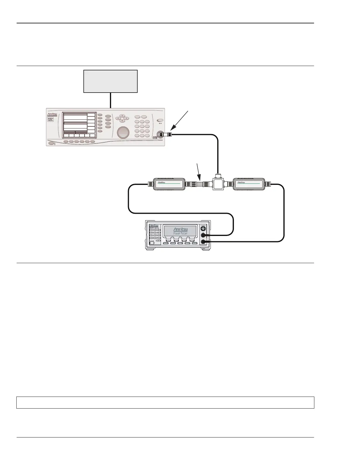
Test Setup Component Characterization
1. Connect both MA2442D power sensors to the power meter and calibrate the sensors.
2. Connect the equipment as shown in Figure 2-3.
3. Set the power meter to display both Channel A and Channel B. Press the Sensor key, the Cal Factor soft
key, and then the Freq soft key. Use the keypad to enter the value matching the frequency of the
MG3692x as the input signal frequency, which sets the power meter to the proper power sensor
calibration factor. Repeat for Channel B. Press the System key to display the power reading.
4. Set the MG3692x frequency to 10.1 MHz and adjust the level so that the Sensor A reading
is –2 dBm ± 0.1 dB.
5. Record the Sensor B reading into the –2 dBm column of Table A-7, “Spectrum Analyzer Absolute
Amplitude Accuracy Across Frequency Setup Table” on page A-6.
6. Adjust the MG3692x output level so that the Sensor A reading is –30 dBm ± 0.1 dB.
7. Record the Sensor B reading into the –30 dBm column of Table A-7.
8. Adjust the MG3692x output level so that the Sensor A reading is –50 dBm ± 0.1 dB.
9. Record the Sensor B reading into the –50 dBm column of Table A-7
10. Repeat Step 2 through Step 9 for all of the frequencies that are listed in Table A-7.
Figure 2-3. Fixed Level with Varying Frequency Setup
Caution Before continuing, allow a 30 minute warm-up for the internal circuitry to stabilize.
MG3692x Synthesized Signal Generator
10 MHz
Reference
ML2438A Power Meter
MA2442D
Sensor A
MA2442D
Sensor B
1870A
Power Splitter
10 dB Fixed
Attenuator
Adapter
A
B