CPS100 SERIES OPERATION MANUAL
SECTION 8:
Master Slave Operation
Entire Contents Copyright 2018 by Adaptive Power Systems, Inc. (APS) • All Rights Reserved • No reproduction without written authorization from APS.
APS CPS100 Series Power Source Operation Manual Page 179 of 231
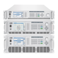
8.5.2 Series Mode System Use
For this configuration, there is one Master and only one Slave so there are 2 units. The
Master unit must be set to Mode = Master, Master Type = Series as shown in the screens
below.
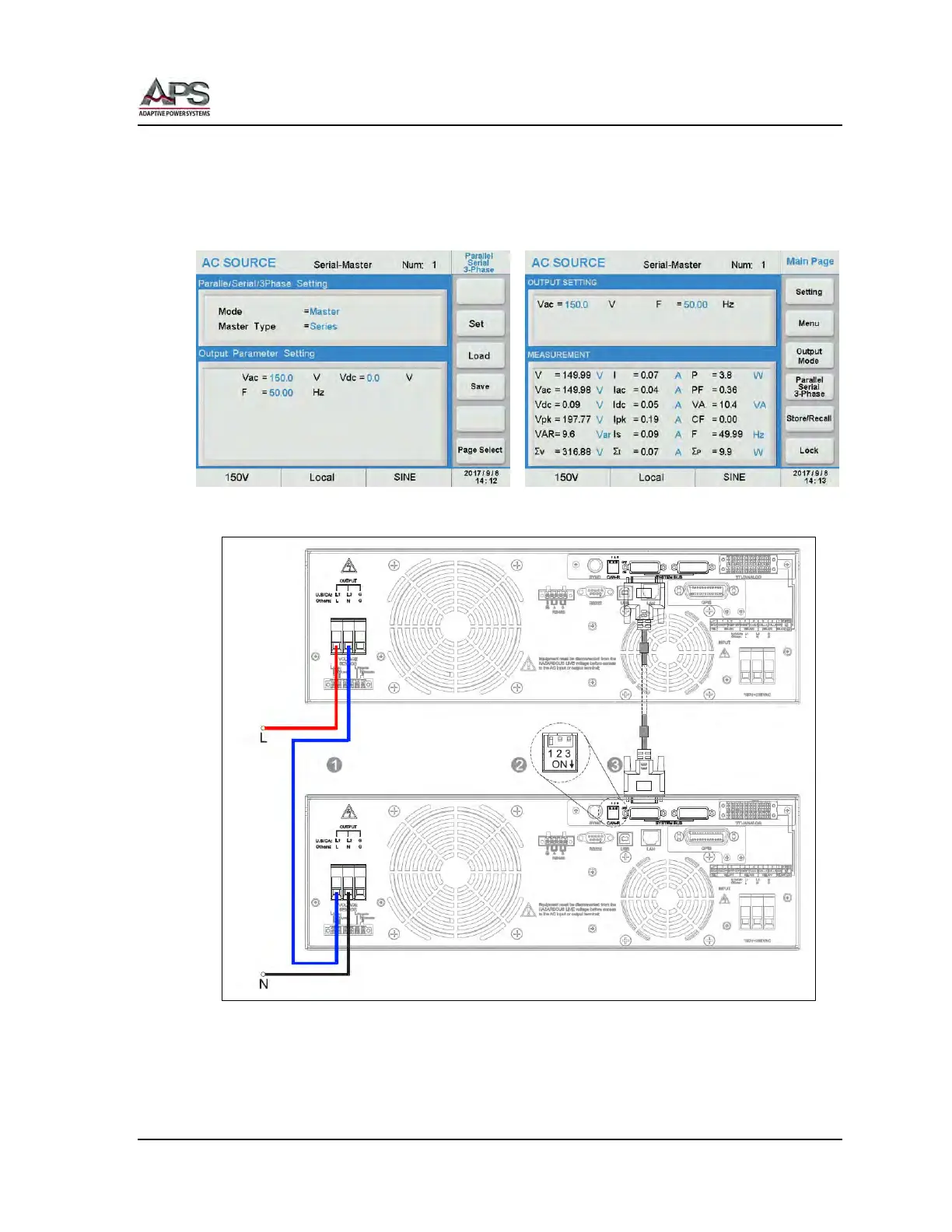
8.5.2.1 Series Mode Connection Diagram
Call outs:
1. Output Connections
2. Termination resistor CAN-R, Flip Dip Switch 1 to ON Position (down)
3. System Bus Communication Cable