CHAPTER 2, CONTROLS AND DISPLAY
EFD1000 PFD Pilot’s Guide
Page 2-18 A-01-184-00 REV B
EFD1000 PFD Pilot’s Guide
EFD1000 PFD Pilot’s Guide
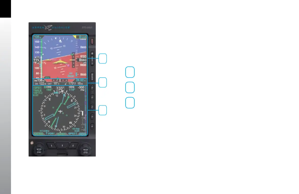
2.3. Display
The EFD1000 Pro PFD replaces the existing Attitude Indicator and HSI or DG in the
center of the primary ight instrument cluster. Like the instruments it replaces, the top
half presents an Attitude Display and the bottom half presents a Navigation Display
(Figure 2-26). Between the two halves is a Data Bar, which presents a dedicated
display of real-time winds and temperatures, as well as True Airspeed (TAS) and GPS
Ground Speed (GS).
1
Attitude Display
2
Databar
3
Navigation Display
Unlike the mechanical indicators it typically replaces, EFD1000 PFD can also display all
the data provided by the remaining four instruments in the “six pack” (airspeed, altitude,
turn and slip, and vertical speed), as well as much more. Concentrating all primary ight
information onto a single instrument directly in front of the pilot improves instrument
scan and reduces pilot workload, thereby enhancing safety, especially in busy phases
of ight. Additionally, analog backup primary instruments remain in the pilot’s primary
eld of view, and should be included in the instrument scan to cross-check indications
of both the primary (EFIS) and backup (analog) instruments.
Figure 2-26 EFD1000 Pro PFD Display Areas
1
2
3