CHAPTER 2, CONTROLS AND DISPLAY
EFD1000 PFD Pilot’s Guide
Page 2-22 A-01-184-00 REV B
EFD1000 PFD Pilot’s Guide
EFD1000 PFD Pilot’s Guide
2.3.1.1. Attitude Director Indicator (ADI)
The Attitude Director Indicator (ADI) features a conventional blue (sky) over brown
(ground) background, with a white horizon line dividing the two areas. A triangular
aircraft reference symbol (Ref. 17) is in a xed position, and shows aircraft attitude
relative to the horizon.
The pitch scale (or ladder) indicates degrees of nose up (blue) or nose down (brown)
pitch relative to the apex of the aircraft symbol. Minor pitch marks are shown every
2.5º up to +/-20º of pitch, with major pitch marks every 10º up to +/-90º of pitch. The
distance between pitch marks is greater than on most mechanical attitude indicators,
making it easier for the pilot to y more precise pitch attitudes.
At extreme pitch attitudes (above 50º nose up or below 30º nose down), red Unusual
Attitude Recovery chevrons appear, pointing towards the horizon. At extreme pitch
attitudes, some sky (blue) or ground (brown) will always be displayed to help maintain
situational awareness, even though the horizon line may be o-scale.
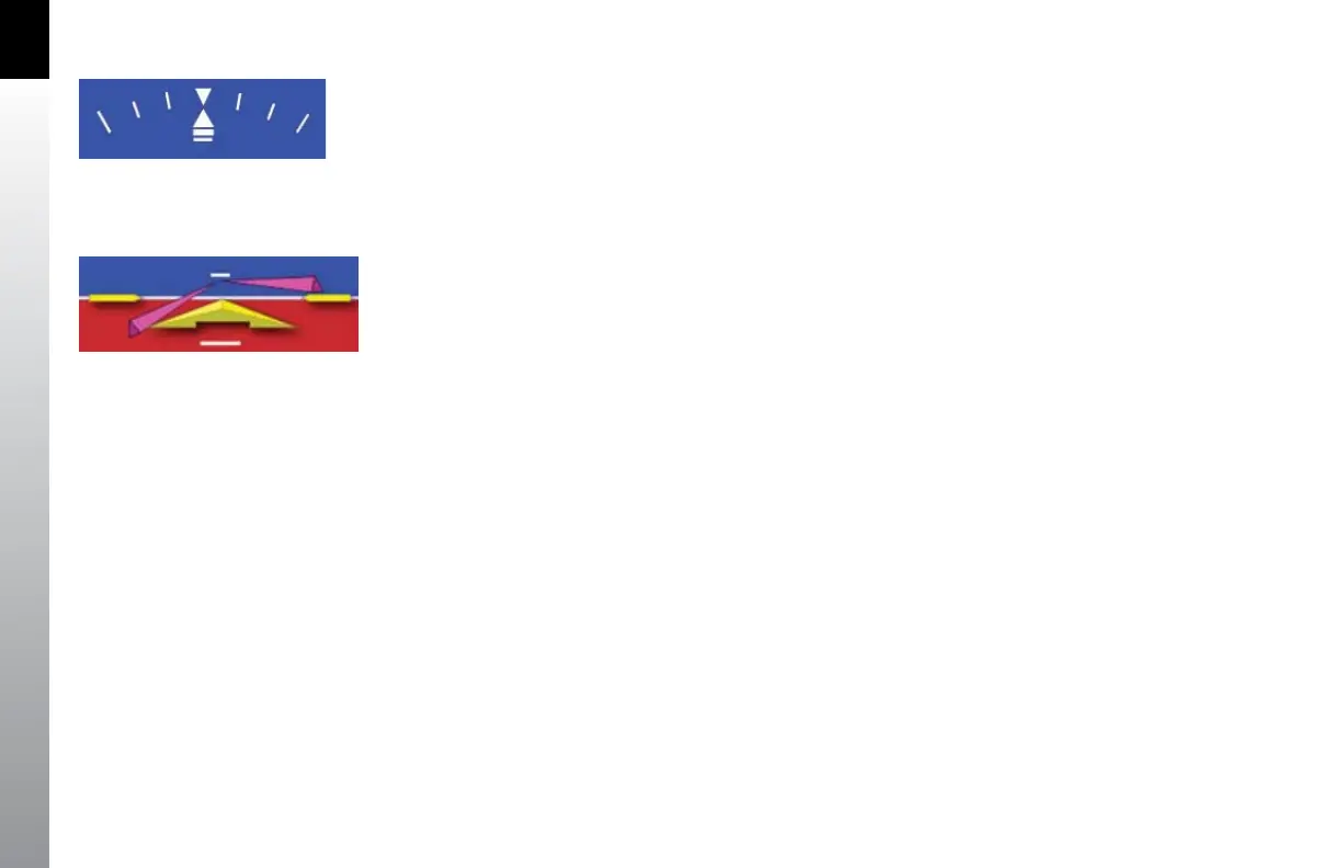
At the top of the ADI are the roll scale, roll pointer, and slip/skid indicator (Figure 2-28).
The roll scale is indicated by tick marks at 10º, 20º, 30º, 45º, and 60º on both sides of the
zero roll inverted solid white triangle. The 45º marks are represented as hollow triangles.
Slip/skid is indicated by the lateral position of the white rectangle under the roll pointer.
One rectangle width is equivalent to one ball width of a conventional inclinometer.
When connected to a compatible autopilot system the EFD1000 will display a single-
cue Flight Director (Figure 2-29). The Flight Director command bars visually represent
the lateral and vertical steering cues transmitted to the EFD by the autopilot. When the
FD output from the autopilot is unavailable or agged invalid, the FD command bars
are removed from the display.
Figure 2-28
Slip/Skid
Figure 2-29
Flight Director