CHAPTER 1, WELCOME
EFD1000 PFD Pilot’s Guide
Page 1-4 A-01-184-00 REV B
EFD1000 PFD Pilot’s Guide
EFD1000 PFD Pilot’s Guide
Digital GPS/VLOC
Analog GPS/VLOC via ACU
EFD1000 PFD
(Primary Flight Display)
Analog
Converter Unit
(ACU)
Aircraft Power
Configuration Module
Optional T o ne Generator
12C
SPI
RS-232
Digital VLOC/GPS
Sources
Analog NAV Sources
Radar Altimeter
Autopilot
Legacy GPS
RS-232
Discrete
Pitot Static
Existing Aircraft
Static Line
Existing Aircraft
Pitot Line
Remote
Sensor
Module
(RSM)
ARINC 429
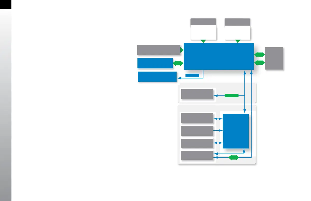
Figure 1-5 EFD 1000 System Architecture
1.1. System Overview
The EFD1000 Pro PFD system typically consists of
four components:
1. EFD1000 Display Unit
2. Conguration Module (CM)
3. Remote Sensor Module (RSM)
4. Analog Converter Unit (ACU)
The ACU converts older analog signals and interfaces
to the industry-standard digital ARINC 429 interface,
which is the native language of the EFD1000. In
some installations, generally when the aircraft is not
equipped with an autopilot and has only digital GPS/
nav/comms, the ACU may be omitted.
The system architecture in (Figure 1-5) shows the
relationships of the PFD, RSM, Conguration Module
and ACU.