EFD1000 PFD Pilot’s Guide
CHAPTER 2, CONTROLS AND DISPLAY
EFD1000 PFD Pilot’s Guide
EFD1000 PFD Pilot’s Guide Page 2-25A-01-184-00 REV B
2.3.1.4. Instrument Approach Indicators
Additional indicators are shown or available on the Attitude Display when ying
certain types of instrument approaches. These enable the pilot to maintain a tighter
instrument scan on the ADI, reducing workload and improving safety (Figure 2-32).
A Lateral Deviation Indicator (LDI, (Figure 2-2, No. 35)) is presented on the attitude
indicator whenever the pilot has coupled an ILS, LOC, LOC(BC), or a GPS in Approach
Mode to the HSI, and valid lateral guidance is being provided. The navigation source
coupled to the LDI is annunciated to the left of the LDI (Figure 2-2, No. 29).
A Vertical Deviation Indicator (VDI, (Figure 2-2, No. 34)) is presented on the attitude
indicator whenever the LDI is shown and valid vertical guidance is provided, such as
from an ILS or WAAS GPS.
Whenever the lateral or vertical deviation exceeds the maximum displayable range of
2.5 dots, the deviation diamond is rendered as a hollow, ghosted image pegged to the
corresponding side. As soon as the deviation comes into range, the diamond turns
solid green, making it easy to identify when the needle is alive.
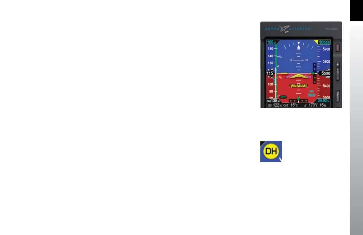
Additionally, the pilot can pre-set the minimums (MIN) for the approach, which will be
displayed on the ADI (Figure 2-2, No. 28) until the pilot toggles o the display using
the MIN hot key. Once the MIN data eld value is set to a Decision Altitude or Minimum
Descent Altitude, the EFD1000 PFD provides an alert when the aircraft reaches or
descends below this altitude.
If a Radar Altimeter is installed in the aircraft and connected to the EFD1000, a Decision
Height annunciation (Figure 2-2, No. 26) will be displayed when the aircraft descends
to or below the selected radar altitude (Figure 2-33).
Figure 2-32
Instrument Approach Indications
Figure 2-33
Decision Height Annunciation