R5906848 /04 DP2K SLP Series 101
Image 9-9
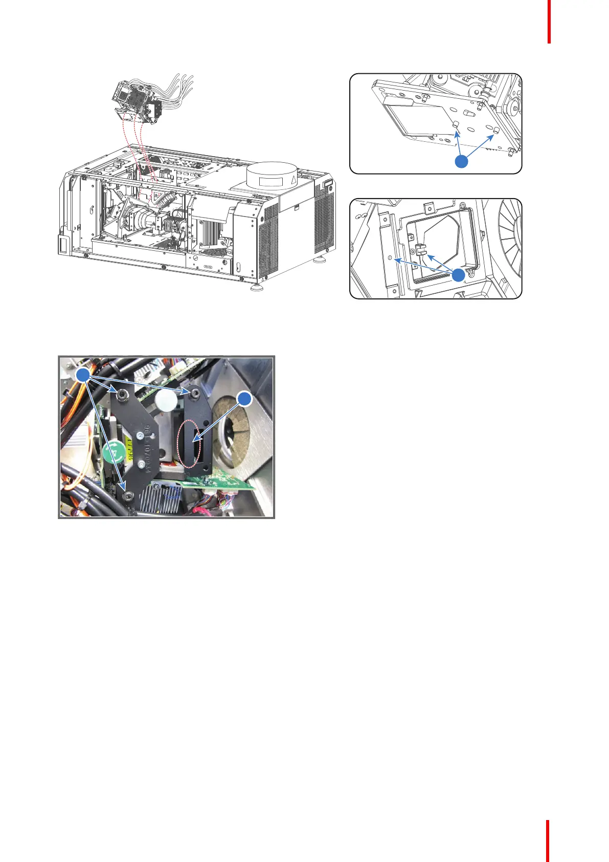
2. Fasten the three captive screws (reference 9 Image 9-10) of the Light Processor assembly as illustrated. Use
a 3mm Allen wrench.
Image 9-10
3. Connect the nine RGB connectors (reference 1 to 9 of Image 9-11) with the Signal Distribution board as
illustrated.
• Reference 1 - small connector with blue cable tie.
• Reference 2 - small connector with green cable tie.
• Reference 3 - small connector with red cable tie.
• Reference 4 - connector with two blue cable tie.
• Reference 5 - connector with two green cable tie.
• Reference 6 - connector with two red cable tie.
• Reference 7 - connector with one blue cable tie.
• Reference 8 - connector with one green cable tie.
• Reference 9 - connector with one red cable tie.
Light Processor

 Loading...


