R5906848 /04 DP2K SLP Series102
Image 9-11
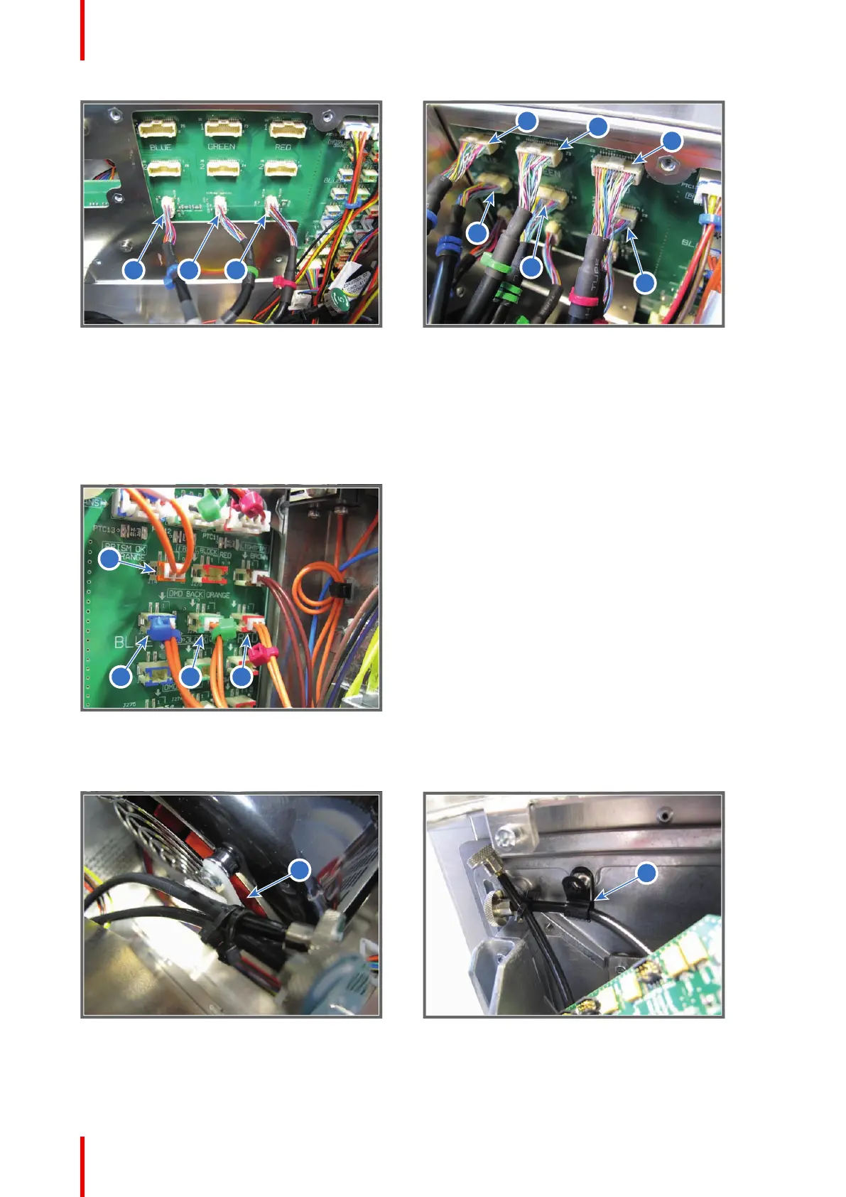
4. Connect the four orange wires of the Light Processor with the Signal Distribution board as illustrated in
Image 9-12.
• Reference 5 - Prism Sensor: orange wire without cable tie.
• Reference 6 - Temperature Sensor DMD Blue Channel: orange wire with blue cable tie.
• Reference 7 - Temperature Sensor DMD Green Channel: orange wire with green cable tie.
• Reference 8 - Temperature Sensor DMD Red Channel: orange wire with red cable tie.
Image 9-12
5. Gently insert the Convergence flex cables into the corresponding cable clamp on the Anode Fan assembly
and the cable clamp on the projector chassis (reference 1 & 2 Image 9-13).
Image 9-13
6. Place the top fan of the Light Processor in the lower position. Ensure that the four mounting pins (reference 1
Image 9-14) of the fan assembly are engaged.
Light Processor

 Loading...


