R5906848 /04 DP2K SLP Series 237
Image 18-42
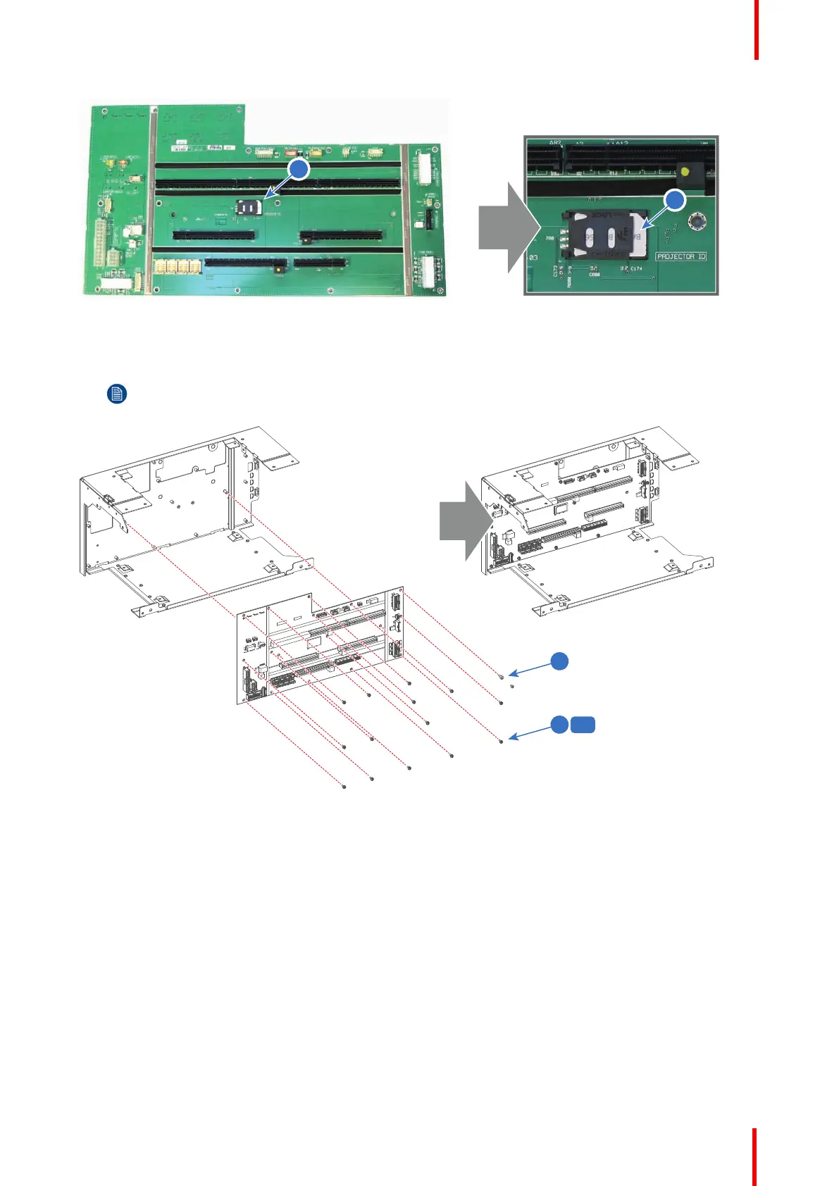
2. Install the Signal Backplane board onto the sub-assembly. Use a T10 Torx driver to fasten the 14 screws
(reference 6 Image 18-43) and use a 5.5 mm nut driver to fasten the plastic spacer (reference 7 Image 18-43)
Note: The plastic spacer is needed at the upper right corner of the Signal Backplane to mount the
temperature sensor afterwards.
Image 18-43
3. Assemble the Card Cage as illustrated. Use a 2.5mm Allen wrench to fasten all twelve screws (reference 1, 2,
3, 4 and 5 Image 18-44) as indicated on the drawing.
Card Cage

 Loading...


