R5906848 /04 DP2K SLP Series98
Image 9-2
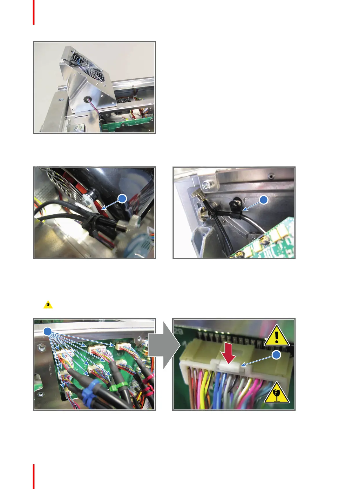
2. Disengage the Convergence flex cables from the cable clamp on the Anode Fan assembly (green channel,
reference 1 Image 9-3) and the cable clamp on the projector chassis (blue channel, reference 2 Image 9-3).
Image 9-3
3. Disconnect the nine RGB connectors (reference 3 Image 9-4) from the Signal Distribution board. Push the
little tab (reference 4 Image 9-4) down with your fingernail and then pull the connector gently out of its socket.
The connector should come out easily from its socket.
Caution: Always push-in the little tab of the connector to remove the connector from its socket.
Neglecting this will result in irreversible damage of the socket.
Image 9-4
4. Disconnect the other four orange wires of the Light Processor from the Signal Distribution board (reference 5,
6, 7 & 8 of Image 9-5).
Light Processor

 Loading...


