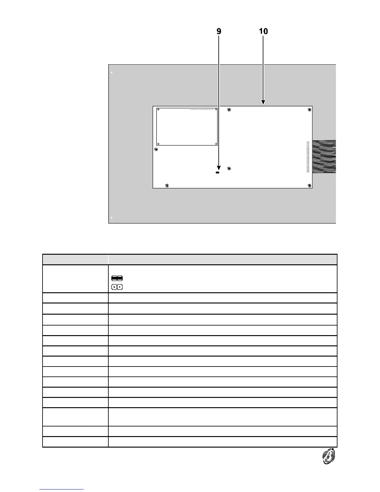
PART DESCRIPTION
9
Jumper to enable programming:
> programming enabled (default)
> programming disabled
10 Keypad/Display board
11
Cable passage (3 x ∅ 30 mm)
12
Wall mounting holes (4 x ∅ 5 mm)
13 6 Output expander FC200/6OUT (optional - 2 maximum)
14 Telecom module FC200/COM (optional)
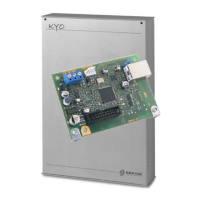
15 Main board
16 27.6 V - 4 A linear power supply/battery charger
17 27.6 V - 2.5 A switching power supply/battery charger
18 Battery connectors
19 Compartment for two (optional)12 V, 17 Ah batteries
20 Jumper for series connection of batteries
21
Bag holding: two F 250V 3.15A fuses; one F 250V 6.3A fuse; two keys;
four 1N4007 diodes; jumper for series connection of batteries
22 Chased cable passage (40 x 170 mm)
23 Loop interface
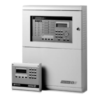
14 Analogue Fire Control Panel FireClass200